
Hyundai Ioniq (AE): Seat Electrical / Seat Heater Switch. Schematic diagrams
Hyundai Ioniq (AE) 2017-2022 Service & Repair Manual / Body Electrical System / Seat Electrical / Seat Heater Switch. Schematic diagrams
| Circuit Diagram |
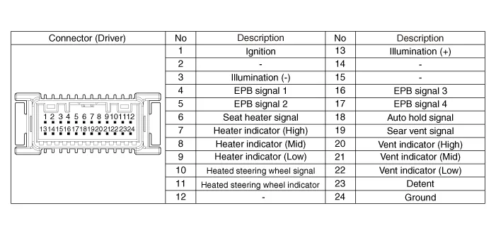
[Front Seat Heater Switch (Driver)]

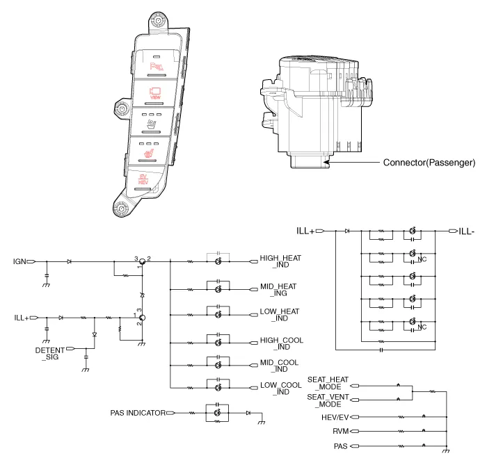
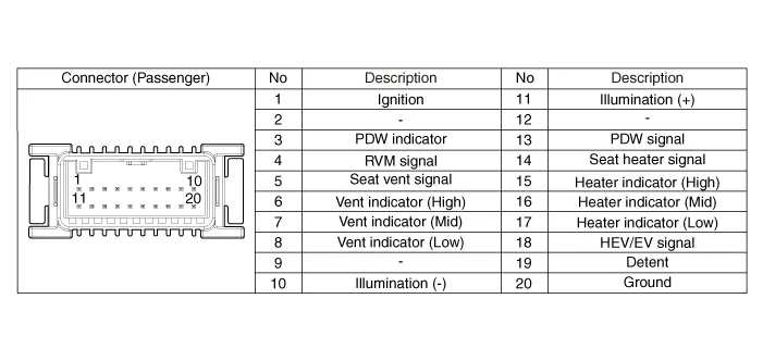
[Front Seat Heater Switch (Passenger)]
[Rear Seat]
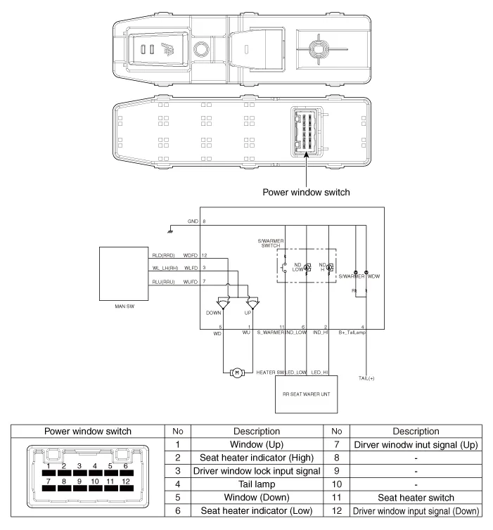
Components[Front Seat]1. Driver seater heater switch2. Passenger seater heater switch[Rear Seat]1. Seat heater switch
Removal[Front Seat]1.Disconnect the negative (-) battery terminal.2.Remove the floor console upper cover.(Refer to Body - "Floor Console Assembly")3.Remove the seat heater switch after loosening mounting screws.
Other information:
Hyundai Ioniq (AE) 2017-2022 Service & Repair Manual: Auto Defogging Sensor. Description and operation
DescriptionThe auto defogging sensor is installed on the front window glass. The sensor judges and sends signal if moisture occurs to blow out wind for defogging. The air conditioner control module receives signal from the sensor and restrains moisture and eliminate defog by controlling the intake actuator, A/C, auto defogging actuator, blower moto
Hyundai Ioniq (AE) 2017-2022 Service & Repair Manual: Smart Cruise Control (SCC) Switch. Components and components location
C
Categories
- Manuals Home
- Hyundai Ioniq Owners Manual
- Hyundai Ioniq Service Manual
- Troubleshooting
- Body (Interior and Exterior)
- Description and operation
- New on site
- Most important about car

Copyright В© 2026 www.hioniqae.com - 0.0177