Hyundai Ioniq (AE): Front Radar System / Smart Cruise Control (SCC) Switch. Components and components location
Hyundai Ioniq (AE) 2017-2022 Service & Repair Manual / Advanced Driver Assistance System (ADAS) / Front Radar System / Smart Cruise Control (SCC) Switch. Components and components location
| Components |
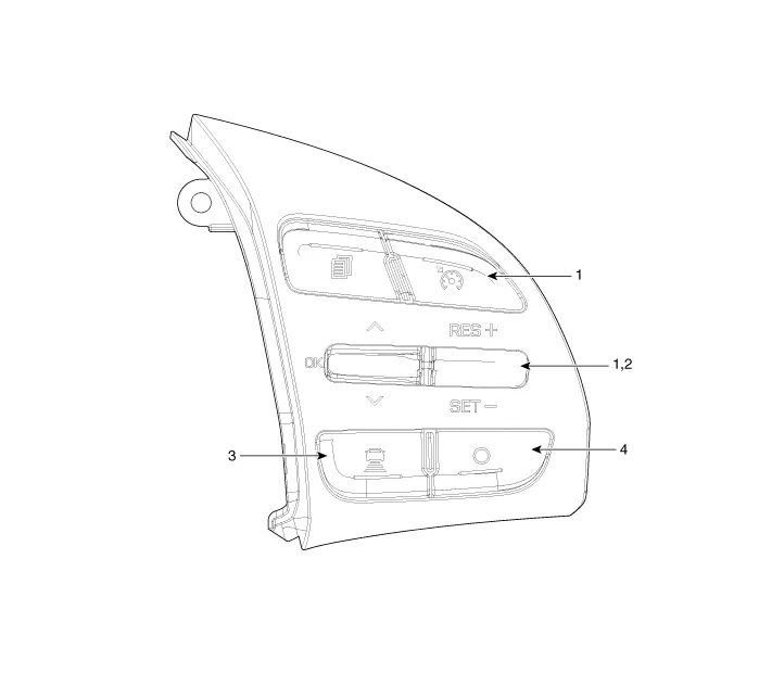
| 1. SET - switch 2. RES + switch 3. Distance setting switch | 4. CANCEL switch 5. CRUISE switch |
Removal1.Remove the front bumper.(Refer to Body - "Front Bumper")2.Disconnect the smart cruise control unit connector (A).3.Remove the smart cruise control nuit assembly (B) from thevehicle after loosening mounting bolts.
Circuit Diagram[Curise + SCC]
Other information:
Hyundai Ioniq (AE) 2017-2022 Service & Repair Manual: Description and operation
DescriptionIn ordinary cars, the mechanical water pump mounted on the engine for heating purposes is activated to circulate the cooling water, but in hybrid cars, AEWP is used to circulate the cooling water when the engine is not operating. Classification System Cooling water used
Hyundai Ioniq (AE) 2017-2022 Service & Repair Manual: Front Radar Unit. Specifications
S
Categories
- Manuals Home
- Hyundai Ioniq Owners Manual
- Hyundai Ioniq Service Manual
- Hybrid Vehicle Engine Compartment
- Repair procedures
- If the 12 Volt Battery is Discharged (Hybrid Vehicle)
- New on site
- Most important about car

Copyright © 2026 www.hioniqae.com - 0.013