Hyundai Ioniq (AE): SRSCM / SRS Control Module (SRSCM). Repair procedures
| Removal |
| 1. | Remove the ignition key from the vehicle. |
| 2. | Disconnect the battery negative cable and wait for at least three minutes before beginning work. |
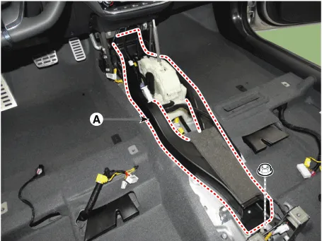
| 3. | Remove the floor console. (Refer to Body - "Floor Console Assembly") |
| 4. | Remove the center console duct (A) after loosening the mounting nut.
|
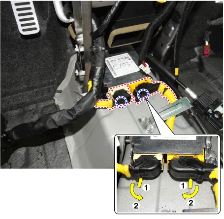
| 5. | Disconnect the SRSCM connectors.
|
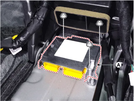
| 6. | Remove the SRSCM (A) after loosening the mounting nuts.
|
| Installation |
| 1. | Remove the ignition key from the vehicle. |
| 2. | Disconnect the battery negative cable and wait for at least three minutes before beginning work. |
| 3. | Install the SRSCM (A) with the SRSCM mounting nuts.
|
| 4. | Connect the SRSCM harness connectors. |
| 5. | Install the heater ducts and floor console. (Refer to Body - "Floor Console Assembly") |
| 6. | Reconnect the battery negative cable. |
| 7. | After installing the SRSCM, confirm proper system operation : Turn the ignition switch ON; the SRS indicator light should be turned on for about six seconds and then go off.
|

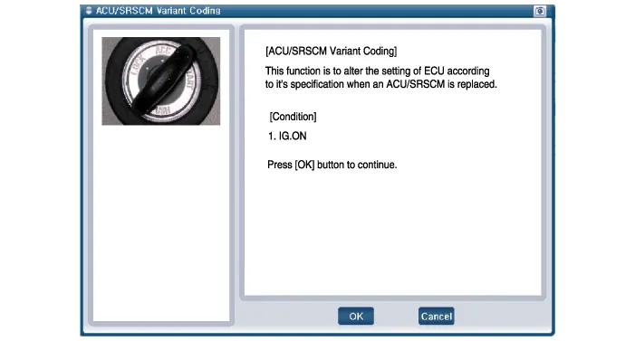
| Variant Coding |
|

| â– On-line Type on GDS |
| 1. | Turn the ignition switch OFF. |
| 2. | Connect the GDS. |
| 3. | Turn the ignition switch ON without the engine running. |
| 4. | Select vehicle name and airbag system. |
| 5. | Select variant coding mode. |
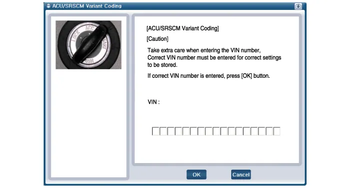
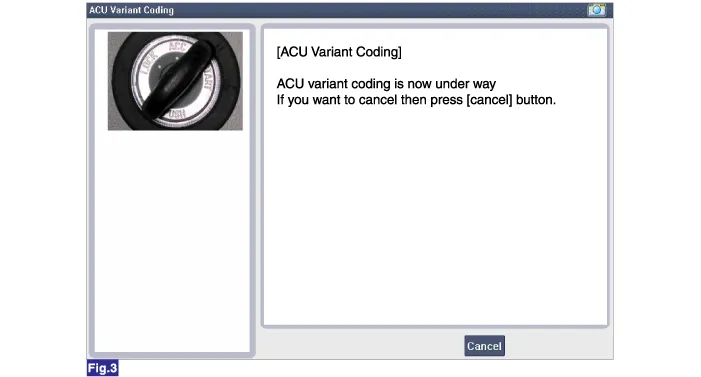
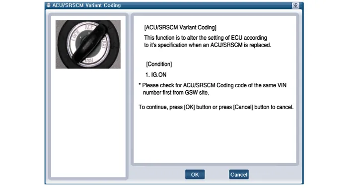
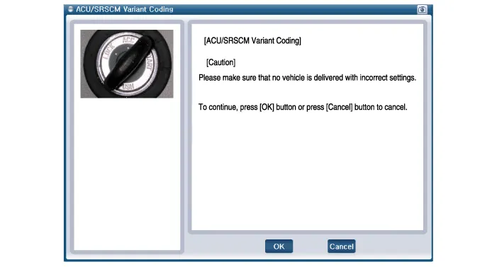
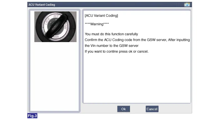
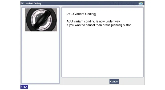
| 6. | Follow the steps on the screen below.
|
|
| â– OFF-Line Type on GDS (Use When Not Connected to the Internet) |
| 1. | Turn the ignition switch OFF. |
| 2. | Connect the GDS. |
| 3. | Turn the ignition switch ON without the engine running. |
| 4. | Select vehicle name and airbag system. |
| 5. | Select variant coding mode. |
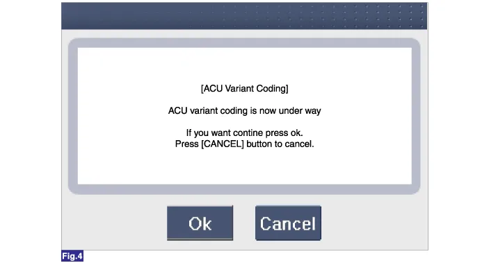
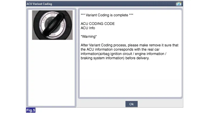
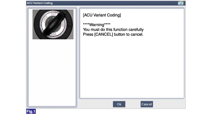
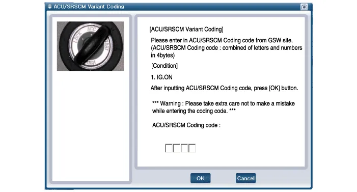
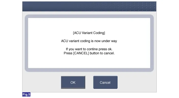
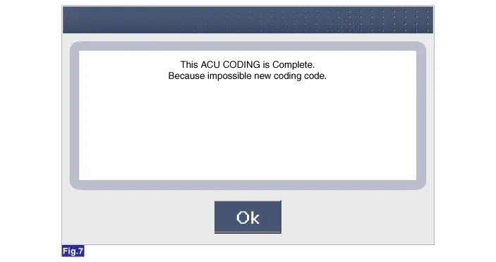
| 6. | Follow the steps on the screen below.
|
Components1. Supplemental Restraint System Control Module (SRSCM)Supplemental Restraint System Control Module (SRSCM) No Connector A Connector B 1IGN 1Ground2Driver front impact sensor - High (+)Driver seat belt pretensioner - High (+)3Driver front impact sensor - Low (-)Driver seat belt pretensioner - Low (-)4Driver airbag 1st stage - High (+)-5Driver airbag 1st stage - Low (-)-6Passenger airbag 1st stage - Low (-)Driver side airbag - High (+)7Passenger airbag 1st stage - High (+)Driver side airbag - Low (-)8Passenger airbag ON/OFF switch - Low (-)Passenger side airbag - Low (-)9Passenger airbag ON/OFF switch - High (+)Passenger side airbag - High (+)10Crash signal outputDriver side impact sensor - High (+)11Passenger front impact sensor - High (+)Driver side impact sensor - Low (-)12Passenger front impact sensor - Low (-)Passenger side impact sensor - Low (-)13-Passenger side impact sensor - High (+)14--15-Passenger seat belt pretensioner - High (+)16-Passenger seat belt pretensioner - Low (-)17P-CAN (High)-18P-CAN (Low)-19-Driver curtain airbag - High (+)20PAB OFF LampDriver curtain airbag - Low (-)21PAB ON LampPassenger curtain airbag - Low (-)22Driver Knee Airbag - High (+)Passenger curtain airbag - High (+)23Driver Knee Airbag - Low (-)Driver Passenger side impact sensor - High (+)24-Driver pressure side impact sensor - Low (-)25-Passenger pressure side impact sensor - Low (-)26C-CAN (High)Passenger Passenger side impact sensor - High (+)27C-CAN (Low)-28-29-30-31-32-33-34-35-36-37-38-39-
Description• The front impact sensors (FIS) are installed on the upper of the side panel in Front End Module (FEM). They are remote sensors that detect acceleration due to a collision at their mounting locations.
Other information:
Hyundai Ioniq (AE) 2017-2022 Service & Repair Manual: Components and components location
C
Hyundai Ioniq (AE) 2017-2022 Service & Repair Manual: Description and operation
DescriptionBlcok DiagramFunctions of Front View CameraFront View Camera supports the following functions using the information (lane, light source, vehicle and pedestrian) detected by the front view camera and the vehicle's signal information (CAN communication).
Categories
- Manuals Home
- Hyundai Ioniq Owners Manual
- Hyundai Ioniq Service Manual
- What to do in an emergency
- Hybrid Control System
- Engine Control/Fuel System
- New on site
- Most important about car
