Hyundai Ioniq (AE): Engine Control System / Accelerator Position Sensor (APS). Schematic diagrams
| Circuit Diagram |
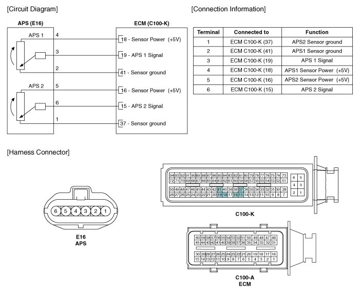
Specification Accelerator Position Output Voltage (V) APS1 APS2 C.
Inspection1.Connect the GDS on the Data Link Connector (DLC).2.Turn the ignition switch ON.3.Measure the output voltage of the APS 1 and 2 at C.T and W.
Other information:
Hyundai Ioniq (AE) 2017-2022 Service & Repair Manual: Ambient Temperature Sensor. Description and operation
DescriptionThe ambient temperature sensor is located at the front of the condenser and detects ambient air temperature. It is a negative type thermistor; resistance will increase with lower temperature, and decrease with higher temperature.The sensor output will be used for discharge temperature control, temperature regulation door contrl, blower m
Hyundai Ioniq (AE) 2017-2022 Service & Repair Manual: Smart Cruise Control (SCC) Switch. Repair procedures
Removal1.Disconnect the negative (-) battery terminal.2.Remove the steering wheel assembly.(Refer to Steering System -"Steering Wheel")3.Remove the steering back cover (A).4.Remove the steering remote control connector (A).5.Remove the steering remote control (A), after loosening the screws.
Categories
- Manuals Home
- Hyundai Ioniq Owners Manual
- Hyundai Ioniq Service Manual
- Jump Starting
- Heating, Ventilation and Air Conditioning
- Suspension System
- New on site
- Most important about car
