Hyundai Ioniq (AE): High Voltage Battery Control System / BMS ECU. Schematic diagrams
Hyundai Ioniq (AE) 2017-2022 Service & Repair Manual / Hybrid Control System / High Voltage Battery Control System / BMS ECU. Schematic diagrams
| BMS ECU Terminal and Input/Output Signal |
| Terminal Funxtion |
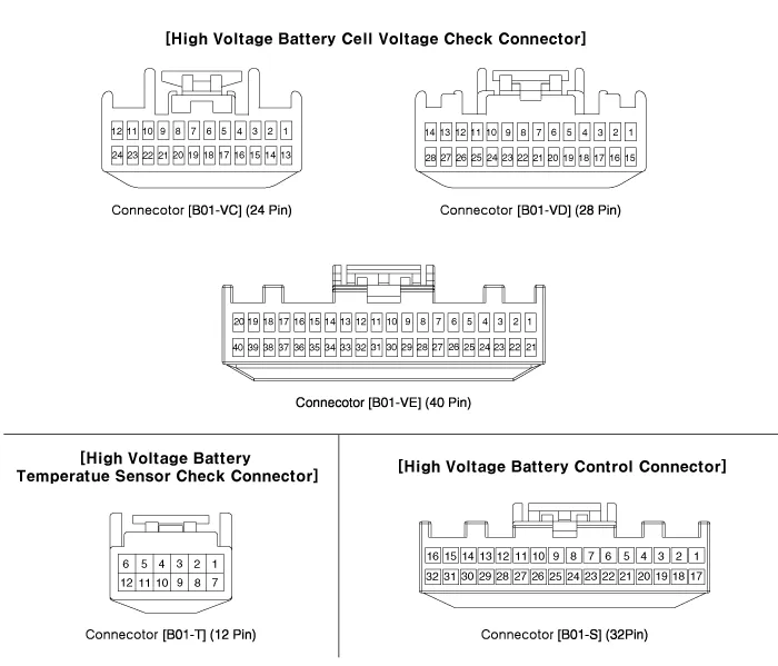
Connector [B01-VC] (24pin) : High Voltage Battery Cell Voltage Check Connector
|
Pin No
|
Description
|
Connected to
|
| 1 | - | - |
| 2 | - | - |
| 3 | - | - |
| 4 | Battery Voltage [Module 1/ Cell 0] signal input | Battery Module [1] |
| 5 | Battery Voltage [Module 1/ Cell 2] signal input | Battery Module [1] |
| 6 | Battery Voltage [Module 1/ Cell 4] signal input | Battery Module [1] |
| 7 | Battery Voltage [Module 1/ Cell 6] signal input | Battery Module [1] |
| 8 | Battery Voltage [Module 1/ Cell 8] signal input | Battery Module [1] |
| 9 | Battery Voltage [Module 2/ Cell 1] signal input | Battery Module [1] |
| 10 | Battery Voltage [Module 2/ Cell 3] signal input | Battery Module [1] |
| 11 | Battery Voltage [Module 2/ Cell 5] signal input | Battery Module [1] |
| 12 | Battery Voltage [Module 2/ Cell 7] signal input | Battery Module [1] |
| 13 | - | - |
| 14 | - | - |
| 15 | - | - |
| 16 | Battery Voltage [Module 1/ Cell 1] signal input | Battery Module [1] |
| 17 | Battery Voltage [Module 1/ Cell 3] signal input | Battery Module [1] |
| 18 | Battery Voltage [Module 1/ Cell 5] signal input | Battery Module [1] |
| 19 | Battery Voltage [Module 1/ Cell 7] signal input | Battery Module [1] |
| 20 | Battery Voltage [Module 2/ Cell 0] signal input | Battery Module [1] |
| 21 | Battery Voltage [Module 2/ Cell 2] signal input | Battery Module [1] |
| 22 | Battery Voltage [Module 2/ Cell 4] signal input | Battery Module [1] |
| 23 | Battery Voltage [Module 2/ Cell 6] signal input | Battery Module [1] |
| 24 | Battery Voltage [Module 2/ Cell 8] signal input | Battery Module [1] |
Connector [B01-VD] (28pin) : High Voltage Battery Cell Voltage Check Connector
|
Pin No
|
Description
|
Connected to
|
| 1 | - |  - |
| 2 | - |  - |
| 3 | - |  - |
| 4 | - |  - |
| 5 | Battery Voltage [Module 3/ Cell 1] signal input | Battery Module [2] |
| 6 | Battery Voltage [Module 3/ Cell 3] signal input | Battery Module [2] |
| 7 | Battery Voltage [Module 3/ Cell 5] signal input | Battery Module [2] |
| 8 | Battery Voltage [Module 3/ Cell 7] signal input | Battery Module [2] |
| 9 | Battery Voltage [Module 4/ Cell 0] signal input | Battery Module [2] |
| 10 | Battery Voltage [Module 4/ Cell 2] signal input | Battery Module [2] |
| 11 | Battery Voltage [Module 4/ Cell 4] signal input | Battery Module [2] |
| 12 | Battery Voltage [Module 4/ Cell 6] signal input | Battery Module [2] |
| 13 | Battery Voltage [Module 4/ Cell 8] signal input | Battery Module [2] |
| 14 | - | - |
| 15 | - | - |
| 16 | - | - |
| 17 | - | - |
| 18 | Battery Voltage [Module 3/ Cell 0] signal input | Battery Module [2] |
| 19 | Battery Voltage [Module 3/ Cell 2] signal input | Battery Module [2] |
| 20 | Battery Voltage [Module 3/ Cell 4] signal input | Battery Module [2] |
| 21 | Battery Voltage [Module 3/ Cell 6] signal input | Battery Module [2] |
| 22 | Battery Voltage [Module 3/ Cell 8] signal input | Battery Module [2] |
| 23 | Battery Voltage [Module 4/ Cell 1] signal input | Battery Module [2] |
| 24 | Battery Voltage [Module 4/ Cell 3] signal input | Battery Module [2] |
| 25 | Battery Voltage [Module 4/ Cell 5] signal input | Battery Module [2] |
| 26 | Battery Voltage [Module 4/ Cell 7] signal input | Battery Module [2] |
| 27 | - | - |
| 28 | - | - |
Connector [B01-VE] (40pin) : High Voltage Battery Cell Voltage Check Connector
|
Pin No
|
Description
|
Connected to
|
| 1 | Battery Voltage [Module 5/ Cell 0] signal input | Battery Module [3] |
| 2 | Battery Voltage [Module 5/ Cell 2] signal input | Battery Module [3] |
| 3 | Battery Voltage [Module 5/ Cell 4] signal input | Battery Module [3] |
| 4 | Battery Voltage [Module 5/ Cell 6] signal input | Battery Module [3] |
| 5 | Battery Voltage [Module 5/ Cell 8] signal input | Battery Module [3] |
| 6 | Battery Voltage [Module 6/ Cell 1] signal input | Battery Module [3] |
| 7 | Battery Voltage [Module 6/ Cell 3] signal input | Battery Module [3] |
| 8 | Battery Voltage [Module 6/ Cell 5] signal input | Battery Module [3] |
| 9 | Battery Voltage [Module 6/ Cell 7] signal input | Battery Module [3] |
| 10 | Battery Voltage [Module 7/ Cell 0] signal input | Battery Module [4] |
| 11 | Battery Voltage [Module 7/ Cell 2] signal input | Battery Module [4] |
| 12 | Battery Voltage [Module 7/ Cell 4] signal input | Battery Module [4] |
| 13 | Battery Voltage [Module 7/ Cell 6] signal input | Battery Module [4] |
| 14 | Battery Voltage [Module 7/ Cell 8] signal input | Battery Module [4] |
| 15 | Battery Voltage [Module 8/ Cell 1] signal input | Battery Module [4] |
| 16 | Battery Voltage [Module 8/ Cell 3] signal input | Battery Module [4] |
| 17 | Battery Voltage [Module 8/ Cell 5] signal input | Battery Module [4] |
| 18 | Battery Voltage [Module 8/ Cell 7] signal input | Battery Module [4] |
| 19 | - | - |
| 20 | - | - |
| 21 | Battery Voltage [Module 5/ Cell 1] signal input | Battery Module [3] |
| 22 | Battery Voltage [Module 5/ Cell 3] signal input | Battery Module [3] |
| 23 | Battery Voltage [Module 5/ Cell 5] signal input | Battery Module [3] |
| 24 | Battery Voltage [Module 5/ Cell 7] signal input | Battery Module [3] |
| 25 | Battery Voltage [Module 6/ Cell 0] signal input | Battery Module [3] |
| 26 | Battery Voltage [Module 6/ Cell 2] signal input | Battery Module [3] |
| 27 | Battery Voltage [Module 6/ Cell 4] signal input | Battery Module [3] |
| 28 | Battery Voltage [Module 6/ Cell 6] signal input | Battery Module [3] |
| 29 | Battery Voltage [Module 6/ Cell 8] signal input | Battery Module [3] |
| 30 | Battery Voltage [Module 7/ Cell 1] signal input | Battery Module [4] |
| 31 | Battery Voltage [Module 7/ Cell 3] signal input | Battery Module [4] |
| 32 | Battery Voltage [Module 7/ Cell 5] signal input | Battery Module [4] |
| 33 | Battery Voltage [Module 7/ Cell 7] signal input | Battery Module [4] |
| 34 | Battery Voltage [Module 8/ Cell 0] signal input | Battery Module [4] |
| 35 | Battery Voltage [Module 8/ Cell 2] signal input | Battery Module [4] |
| 36 | Battery Voltage [Module 8/ Cell 4] signal input | Battery Module [4] |
| 37 | Battery Voltage [Module 8/ Cell 6] signal input | Battery Module [4] |
| 38 | Battery Voltage [Module 8/ Cell 8] signal input | Battery Module [4] |
| 39 | - | - |
| 40 | - | - |
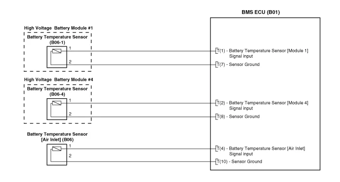
Connector [B01-T] (12pin) : High Voltage Battery Temperatue Sensor Check Connector
|
Pin No
|
Description
|
Connected to
|
| 1 | Battery Temperatue Sensor [Module 1] signal input | Battery Temperatue Sensor |
| 2 | Battery Temperatue Sensor [Module 4] signal input | Battery Temperatue Sensor |
| 3 | - | - |
| 4 | Battery Temperatue Sensor [Air Inlet] signal input | Battery Temperatue Sensor |
| 5 | - | - |
| 6 | - | - |
| 7 | Sensor ground [Module 1] | Battery Temperatue Sensor |
| 8 | Sensor ground [Module 4] | Battery Temperatue Sensor |
| 9 | - | - |
| 10 | Sensor ground [Air Inlet] | Battery Temperatue Sensor |
| 11 | - | - |
| 12 | - | - |
Connector [B01-S] (32pin) : High Voltage Battery Control Connector
|
Pin No
|
Description
|
Connected to
|
| 1 | Battery Power (B+) | BMS Extension Connector BF11 (1) |
| 2 | Battery Power (B+) | BMS Extension Connector BF11 (11) |
| 3 | Battery Power (B+) | BMS Extension Connector BF11 (12) |
| 4 | Cooling fan feedback signal input | BMS Blower Motor |
| 5 | H-CAN [High] | Other Control Module |
| 6 | H-CAN [Low] | Other Control Module |
| 7 | P-CAN [High] | Other Control Module |
| 8 | P-CAN [Low] | Other Control Module |
| 9 | - | - |
| 10 | - | - |
| 11 | Sensor Power (+5V) | Battery Current Sensor [PRA] |
| 12 | Battery Current Sensor signal input | Battery Current Sensor [PRA] |
| 13 | - | - |
| 14 | - | - |
| 15 | Pre-Charge Relay Control | Pre-Charge Relay |
| 16 | Main Relay [+] Control | Main Relay [+] |
| 17 | Ground | Chassis Ground |
| 18 | Ground | Chassis Ground |
| 19 | Cooling Fan Relay Control | BMS Extension Connector BF11 (4) |
| 20 | Cooling Fan Speed signal input | BMS Blower Motor |
| 21 | - | - |
| 22 | - | - |
| 23 | - | - |
| 24 | Clash signal input | BMS Extension Connector BF11 (18) |
| 25 | Safety Plug Interlock signal input | Safety Plug |
| 26 | - | |
| 27 | Sensor ground | Battery Current Sensor [PRA] |
| 28 | - | - |
| 29 | - | - |
| 30 | VPD Relay Control | VPD Relay |
| 31 | - | - |
| 32 | Main Relay [-] Control | Main Relay [-] |
| Circuit Diagram |
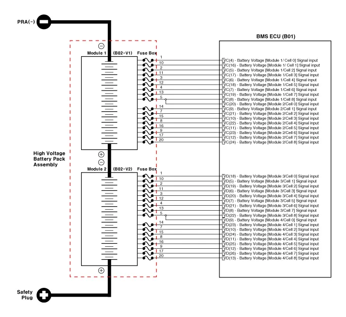
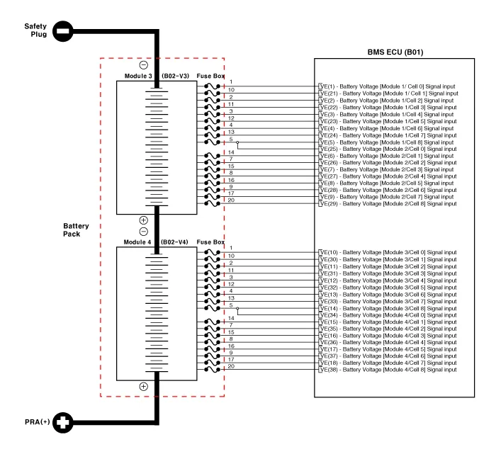
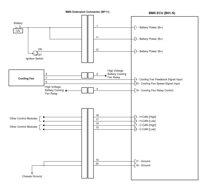
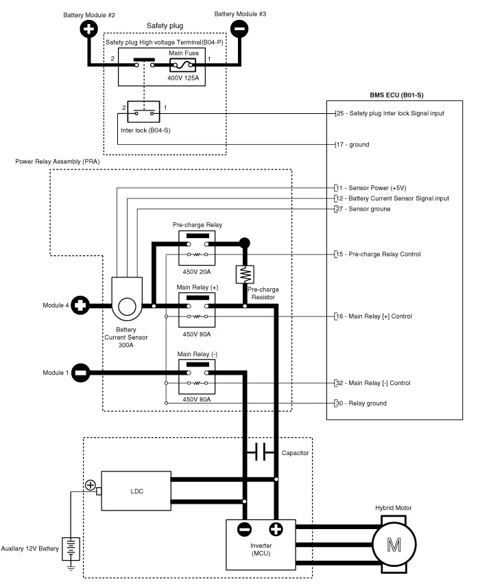
Schematic Diagram
Removal1.Shut off the high voltage.(Refer to Hybrid Control System - "High Voltage Shut-off Procedures")2.Remove the rear seat cushion.(Refer to Body - "Rear Seat Assembly")3.
Other information:
Hyundai Ioniq (AE) 2017-2022 Service & Repair Manual: Duct Sensor. Components and components location
C
Hyundai Ioniq (AE) 2017-2022 Service & Repair Manual: Schematic diagrams
Trouble Symptom ChartsComponent Parts and Function Outline Component part Function Cruise Control Switch Input the set speed and distance to the SCC ECU. Instrument Cluster Display various information inputted from SCC.
Categories
- Manuals Home
- Hyundai Ioniq Owners Manual
- Hyundai Ioniq Service Manual
- Maintenance
- Hybrid Control System
- Engine Clutch System
- New on site
- Most important about car

Copyright © 2026 www.hioniqae.com - 0.0099