Hyundai Ioniq (AE): High Voltage Battery Control System / BMS ECU. Repair procedures
| Removal |
| 1. | Shut off the high voltage. (Refer to Hybrid Control System - "High Voltage Shut-off Procedures") |
| 2. | Remove the rear seat cushion. (Refer to Body - "Rear Seat Assembly") |
| 3. | Remove the rear door scuff trim. (Refer to Body - "Door Scuff Trim") |
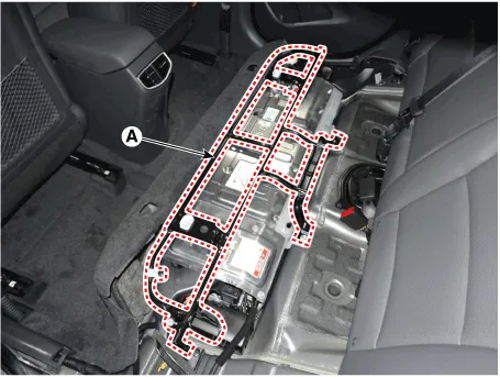
| 4. | Remove the upper frame (A) after loosening the mounting bolts and nuts.
|
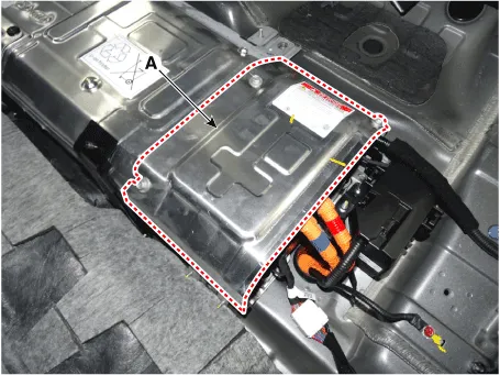
| 5. | Remove the high voltage battery rear cover (A) after loosening the mounting bolts and nuts.
|
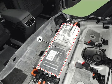
| 6. | Remove the high voltage battery front cover (A) after loosening the mounting bolts and nuts.
|
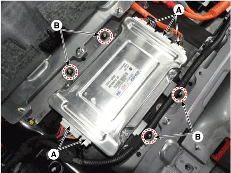
| 7. | Disconnect the BMS connector (A). |
| 8. | Remove the installation nut (B), then remove the BMS.
|
| Installation |
|

| 1. | Install the BMS ECU in the reverse order of removal.
|
BMS ECU Terminal and Input/Output SignalTerminal FunxtionConnector [B01-VC] (24pin) : High Voltage Battery Cell Voltage Check Connector Pin No Description Connected to 1--2--3--4Battery Voltage [Module 1/ Cell 0] signal inputBattery Module [1]5Battery Voltage [Module 1/ Cell 2] signal inputBattery Module [1]6Battery Voltage [Module 1/ Cell 4] signal inputBattery Module [1]7Battery Voltage [Module 1/ Cell 6] signal inputBattery Module [1]8Battery Voltage [Module 1/ Cell 8] signal inputBattery Module [1]9Battery Voltage [Module 2/ Cell 1] signal inputBattery Module [1]10Battery Voltage [Module 2/ Cell 3] signal inputBattery Module [1]11Battery Voltage [Module 2/ Cell 5] signal inputBattery Module [1]12Battery Voltage [Module 2/ Cell 7] signal inputBattery Module [1]13--14--15--16Battery Voltage [Module 1/ Cell 1] signal inputBattery Module [1]17Battery Voltage [Module 1/ Cell 3] signal inputBattery Module [1]18Battery Voltage [Module 1/ Cell 5] signal inputBattery Module [1]19Battery Voltage [Module 1/ Cell 7] signal inputBattery Module [1]20Battery Voltage [Module 2/ Cell 0] signal inputBattery Module [1]21Battery Voltage [Module 2/ Cell 2] signal inputBattery Module [1]22Battery Voltage [Module 2/ Cell 4] signal inputBattery Module [1]23Battery Voltage [Module 2/ Cell 6] signal inputBattery Module [1]24Battery Voltage [Module 2/ Cell 8] signal inputBattery Module [1]Connector [B01-VD] (28pin) : High Voltage Battery Cell Voltage Check Connector Pin No Description Connected to 1- -2- -3- -4- -5Battery Voltage [Module 3/ Cell 1] signal inputBattery Module [2]6Battery Voltage [Module 3/ Cell 3] signal inputBattery Module [2]7Battery Voltage [Module 3/ Cell 5] signal inputBattery Module [2]8Battery Voltage [Module 3/ Cell 7] signal inputBattery Module [2]9Battery Voltage [Module 4/ Cell 0] signal inputBattery Module [2]10Battery Voltage [Module 4/ Cell 2] signal inputBattery Module [2]11Battery Voltage [Module 4/ Cell 4] signal inputBattery Module [2]12Battery Voltage [Module 4/ Cell 6] signal inputBattery Module [2]13Battery Voltage [Module 4/ Cell 8] signal inputBattery Module [2]14--15--16--17--18Battery Voltage [Module 3/ Cell 0] signal inputBattery Module [2]19Battery Voltage [Module 3/ Cell 2] signal inputBattery Module [2]20Battery Voltage [Module 3/ Cell 4] signal inputBattery Module [2]21Battery Voltage [Module 3/ Cell 6] signal inputBattery Module [2]22Battery Voltage [Module 3/ Cell 8] signal inputBattery Module [2]23Battery Voltage [Module 4/ Cell 1] signal inputBattery Module [2]24Battery Voltage [Module 4/ Cell 3] signal inputBattery Module [2]25Battery Voltage [Module 4/ Cell 5] signal inputBattery Module [2]26Battery Voltage [Module 4/ Cell 7] signal inputBattery Module [2]27--28--Connector [B01-VE] (40pin) : High Voltage Battery Cell Voltage Check Connector Pin No Description Connected to 1Battery Voltage [Module 5/ Cell 0] signal inputBattery Module [3]2Battery Voltage [Module 5/ Cell 2] signal inputBattery Module [3]3Battery Voltage [Module 5/ Cell 4] signal inputBattery Module [3]4Battery Voltage [Module 5/ Cell 6] signal inputBattery Module [3]5Battery Voltage [Module 5/ Cell 8] signal inputBattery Module [3]6Battery Voltage [Module 6/ Cell 1] signal inputBattery Module [3]7Battery Voltage [Module 6/ Cell 3] signal inputBattery Module [3]8Battery Voltage [Module 6/ Cell 5] signal inputBattery Module [3]9Battery Voltage [Module 6/ Cell 7] signal inputBattery Module [3]10Battery Voltage [Module 7/ Cell 0] signal inputBattery Module [4]11Battery Voltage [Module 7/ Cell 2] signal inputBattery Module [4]12Battery Voltage [Module 7/ Cell 4] signal inputBattery Module [4]13Battery Voltage [Module 7/ Cell 6] signal inputBattery Module [4]14Battery Voltage [Module 7/ Cell 8] signal inputBattery Module [4]15Battery Voltage [Module 8/ Cell 1] signal inputBattery Module [4]16Battery Voltage [Module 8/ Cell 3] signal inputBattery Module [4]17Battery Voltage [Module 8/ Cell 5] signal inputBattery Module [4]18Battery Voltage [Module 8/ Cell 7] signal inputBattery Module [4]19--20--21Battery Voltage [Module 5/ Cell 1] signal inputBattery Module [3]22Battery Voltage [Module 5/ Cell 3] signal inputBattery Module [3]23Battery Voltage [Module 5/ Cell 5] signal inputBattery Module [3]24Battery Voltage [Module 5/ Cell 7] signal inputBattery Module [3]25Battery Voltage [Module 6/ Cell 0] signal inputBattery Module [3]26Battery Voltage [Module 6/ Cell 2] signal inputBattery Module [3]27Battery Voltage [Module 6/ Cell 4] signal inputBattery Module [3]28Battery Voltage [Module 6/ Cell 6] signal inputBattery Module [3]29Battery Voltage [Module 6/ Cell 8] signal inputBattery Module [3]30Battery Voltage [Module 7/ Cell 1] signal inputBattery Module [4]31Battery Voltage [Module 7/ Cell 3] signal inputBattery Module [4]32Battery Voltage [Module 7/ Cell 5] signal inputBattery Module [4]33Battery Voltage [Module 7/ Cell 7] signal inputBattery Module [4]34Battery Voltage [Module 8/ Cell 0] signal inputBattery Module [4]35Battery Voltage [Module 8/ Cell 2] signal inputBattery Module [4]36Battery Voltage [Module 8/ Cell 4] signal inputBattery Module [4]37Battery Voltage [Module 8/ Cell 6] signal inputBattery Module [4]38Battery Voltage [Module 8/ Cell 8] signal inputBattery Module [4]39--40--Connector [B01-T] (12pin) : High Voltage Battery Temperatue Sensor Check Connector Pin No Description Connected to 1Battery Temperatue Sensor [Module 1] signal inputBattery Temperatue Sensor2Battery Temperatue Sensor [Module 4] signal inputBattery Temperatue Sensor3--4Battery Temperatue Sensor [Air Inlet] signal inputBattery Temperatue Sensor5--6--7Sensor ground [Module 1]Battery Temperatue Sensor 8Sensor ground [Module 4]Battery Temperatue Sensor9--10Sensor ground [Air Inlet]Battery Temperatue Sensor11--12--Connector [B01-S] (32pin) : High Voltage Battery Control Connector Pin No Description Connected to 1Battery Power (B+)BMS Extension Connector BF11 (1)2Battery Power (B+)BMS Extension Connector BF11 (11)3Battery Power (B+)BMS Extension Connector BF11 (12)4Cooling fan feedback signal inputBMS Blower Motor5H-CAN [High]Other Control Module6H-CAN [Low]Other Control Module7P-CAN [High]Other Control Module8P-CAN [Low]Other Control Module9--10--11Sensor Power (+5V)Battery Current Sensor [PRA]12Battery Current Sensor signal inputBattery Current Sensor [PRA]13--14--15Pre-Charge Relay ControlPre-Charge Relay16Main Relay [+] ControlMain Relay [+]17GroundChassis Ground18GroundChassis Ground19Cooling Fan Relay ControlBMS Extension Connector BF11 (4)20Cooling Fan Speed signal inputBMS Blower Motor21--22--23--24Clash signal inputBMS Extension Connector BF11 (18)25Safety Plug Interlock signal inputSafety Plug26-27Sensor groundBattery Current Sensor [PRA]28--29--30VPD Relay ControlVPD Relay31--32Main Relay [-] ControlMain Relay [-]Circuit Diagram
DescriptionSafety Plug is installed on the rear side of the high voltage battery and it can mechanically shut the high voltage circuit off when servicing the high voltage system.
Other information:
Hyundai Ioniq (AE) 2017-2022 Service & Repair Manual: Mode Control Actuator. Repair procedures
Inspection1.Turn the ignition switch OFF.2.Disconnect the mode control actuator connector.3.Verify that the mode control actuator operates to the defrost mode when connecting 12V to terminal 3 and grounding terminal 4.Verify that the mode control actuator operates to the vent mode when connected in reverse.
Hyundai Ioniq (AE) 2017-2022 Service & Repair Manual: Rear Corner Radar Unit. Repair procedures
Removal1.Disconnect the negative (-) battery terminal.2.Remove the rear bumper.(Refer to Body - "Rear Bumper")3.Remove the rear corner radar unit (A) after loosening the mounting nuts. • Take care not to separate the bracket from rear bumper when removing the rear corner radar sensor.
Categories
- Manuals Home
- Hyundai Ioniq Owners Manual
- Hyundai Ioniq Service Manual
- Brake System
- Engine Clutch System
- Jump Starting
- New on site
- Most important about car
