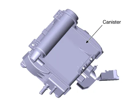
Hyundai Ioniq (AE): Evaporative Emission Control System / Canister. Repair procedures
Hyundai Ioniq (AE) 2017-2022 Service & Repair Manual / Engine Electrical System / Evaporative Emission Control System / Canister. Repair procedures
| Removal |
| 1. | Turn ignition switch OFF and disconnect the negative (-) battery cable. |
| 2. | Remove the fuel tank. (Refer to Engine Control/Fuel System - "Fuel Tank") |
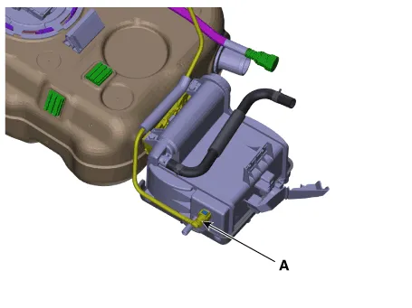
| 3. | Disconnect the vapor tube quick-connector (A).
|
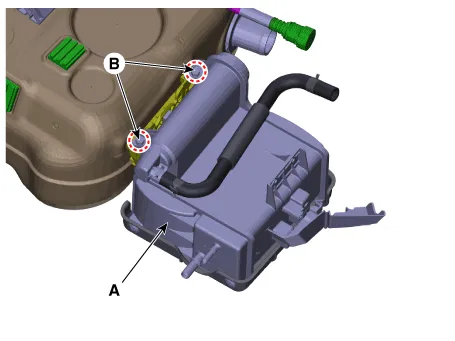
| 4. | Remove the canister (A) from the fuel tank after loosening the bolts (B).
|
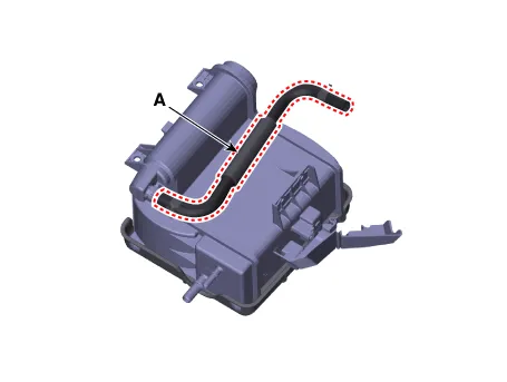
| 5. | Disconnect the vapor hose (A).
|
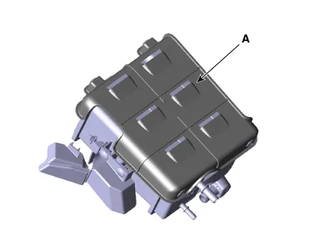
| 6. | Remove the canister protectors (A).
|
| Inspection |
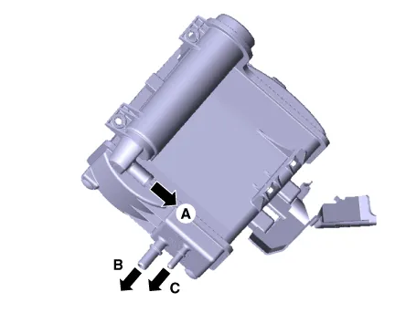
| 1. | Check for the following items visually.
A : Canister ↔ Atmosphere B : Canister ↔ Intake Manifold C : Canister ↔ Fuel Tank |
| Installation |
| 1. | Install in the reverse order of removal. |
Schematic DiagramCanisterCanister is filled with charcoal and absorbs evaporated vapor in fuel tank. The gathered fuel vapor in canister is drawn into the intake manifold by the ECM/PCM when appropriate conditions are set.
Replacement1.Turn ignition switch OFF and disconnect the negative (-) battery cable.2.Remove the filler-neck assembly(Refer to Engine Control/Fuel System - "Filler-Neck Assembly")3.
Other information:
Hyundai Ioniq (AE) 2017-2022 Service & Repair Manual: Auto Defogging Sensor. Repair procedures
Diagnosis With GDS1.The heating, ventilation and air conditioning can be quickly diagnosed failed parts with vehicle diagnostic system (GDS).※ The diagnostic system (GDS) provides the following information.(1) Self diagnosis : Checking the failure code (DTC) and display.
Hyundai Ioniq (AE) 2017-2022 Service & Repair Manual: Components and components location
C
Categories
- Manuals Home
- Hyundai Ioniq Owners Manual
- Hyundai Ioniq Service Manual
- DCT(Dual Clutch Transmission) System
- Heating, Ventilation and Air Conditioning
- Jump starting procedure
- New on site
- Most important about car

Copyright © 2026 www.hioniqae.com - 0.0203