Hyundai Ioniq (AE): Auto Lighting Control System / Components and components location
Hyundai Ioniq (AE) 2017-2022 Service & Repair Manual / Body Electrical System / Auto Lighting Control System / Components and components location
| Component Location |
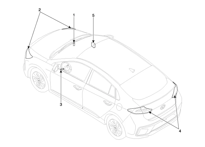
| 1. Auto light sensor 2. Head lamps 3. Lighting switch (Auto) | 4. Rear combination lamp 5. BCM (Body Control Module) |
Specifications Items Specifications Rated voltage5VLoadMax. 1mA (Relay load)Illuminations (LUX)501.
Circuit Diagram
Other information:
Hyundai Ioniq (AE) 2017-2022 Service & Repair Manual: PTC Heater. Description and operation
DescriptionThe PTC (Positive Temperature Coefficient) heater is installed at the exit or the backside of the heater core.The PTC heater is an electric heater using a PTC element as an auxiliary heating device that supplements deficiency of interior heat source in highly effective hybrid engine.
Hyundai Ioniq (AE) 2017-2022 Service & Repair Manual: PTC Heater. Repair procedures
InspectionOperating Logic Test (Manual only)Inspect the PTC operation by confirmation logic as follows.1.Entering(1)Set the Floor mode and maximum heating position.(2)Turn off the blower switch.(3)Press the intake (recirculation) button 5 times or more.
Categories
- Manuals Home
- Hyundai Ioniq Owners Manual
- Hyundai Ioniq Service Manual
- Theft-alarm System
- Hybrid Vehicle Engine Compartment
- Engine Control/Fuel System
- New on site
- Most important about car

Copyright © 2026 www.hioniqae.com - 0.0148