
Hyundai Ioniq (AE): Auto Lighting Control System / Schematic diagrams
Hyundai Ioniq (AE) 2017-2022 Service & Repair Manual / Body Electrical System / Auto Lighting Control System / Schematic diagrams
| Circuit Diagram |
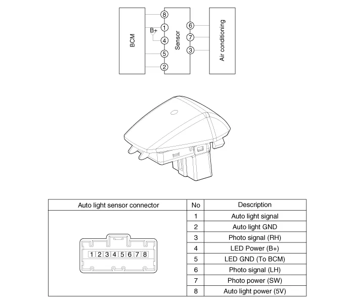
Component Location1. Auto light sensor2. Head lamps3. Lighting switch (Auto)4. Rear combination lamp5. BCM (Body Control Module)
DescriptionIt's a system that uses illumination sensor to automatically turn ON the tail lamp and head lamp based on the change in surrounding environment's illumination condition.
Other information:
Hyundai Ioniq (AE) 2017-2022 Service & Repair Manual: Mode Control Actuator. Components and components location
C
Hyundai Ioniq (AE) 2017-2022 Service & Repair Manual: Description and operation
DescriptionIn ordinary cars, the mechanical water pump mounted on the engine for heating purposes is activated to circulate the cooling water, but in hybrid cars, AEWP is used to circulate the cooling water when the engine is not operating. Classification System Cooling water used
Categories
- Manuals Home
- Hyundai Ioniq Owners Manual
- Hyundai Ioniq Service Manual
- Hybrid Vehicle Engine Compartment
- Jump Starting
- Body (Interior and Exterior)
- New on site
- Most important about car

Copyright В© 2026 www.hioniqae.com - 0.0132