Hyundai Ioniq (AE): Cooling System / Cooling Fan. Repair procedures
| Removal and installation |
| 1. | Disconnect the battery negative terminal. |
| 2. | Remove the air cleaner assembly. (Refer to Intake and Exhaust System - "Air Cleaner") |
| 3. | Disconnect the hybrid starter generator (HSG) coolant hoses (A).
|

| 4. | Disconnect the wire harness connector (A).
|

| 5. | Remove the hood latch assembly. (Refer to Body - "Hood Latch") |
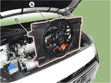
| 6. | Remove the cooling fan upper guard (A).
|

| 7. | Remove the cooling fan (A).
|
| 8. | Install in the reverse order of removal. |
| 1. | Disconnect the battery negative terminal. |
| 2. | Remove the air cleaner assembly. (Refer to Intake and Exhaust System - "Air Cleaner") |
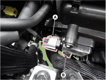
| 3. | Disconnect the wire harness connector (A) and the fan motor connector (B).
|
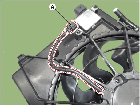
| 4. | Remove the cooling fan controller (PWM) (A) from the cooling fan shroud.
|

| 5. | Install in the reverse order of removal. |
| Disassembly |
| 1. | Remove the cooling fan (A) from the cooling fan assembly.
|

| 2. | Disconnect the fan motor connector (A) from the cooling fan controller (PWM).
|
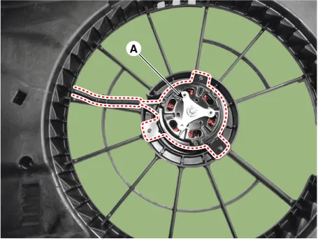
| 3. | Loosen the screws and then remove the fan motor (A) from the cooling fan shroud.
|
| 4. | Assemble in the reverse order of disassembly. |
| Inspection |
| 1. | Disconnect the fan motor connector from the cooling fan controller (PWM). |
| 2. | Connect the battery voltage to the "+" terminal and ground to "-" terminal. |
| 3. | Check the cooling fan motor operates well. |
Schematic Diagrams
Components1. Radiator assembly2. Radiator upper mounting bracket3. Radiator lower hose4. Radiator upper hose5. Mounting insulator6. Clamp
Other information:
Hyundai Ioniq (AE) 2017-2022 Service & Repair Manual: Climate Control Air Filter. Repair procedures
Replacement1.Disconnect the air damper (A) from the glove box (B).2.Remove the stopper (B) from the glove box (A).3.Remove the filter cover (A) by pressing the knob.4.Replace the air filter (A) with a new one according to the direction of air filter. • To remove the filter easily, press the right side inwa
Hyundai Ioniq (AE) 2017-2022 Service & Repair Manual: General safety information and caution
Safety PrecautionPrecautions To Take Before Servicing High Voltage System • Since hybrid vehicles contain a high voltage battery, if the high voltage system or vehicles are handled incorrectly, this might lead to a serious accidents like electric shock and electric leakage.
Categories
- Manuals Home
- Hyundai Ioniq Owners Manual
- Hyundai Ioniq Service Manual
- If the 12 Volt Battery is Discharged (Hybrid Vehicle)
- Engine Control/Fuel System
- General Information
- New on site
- Most important about car
