Hyundai Ioniq (AE): Crash Pad / Crash Pad Garnish. Repair procedures
Hyundai Ioniq (AE) 2017-2022 Service & Repair Manual / Body (Interior and Exterior) / Crash Pad / Crash Pad Garnish. Repair procedures
| Replacement |
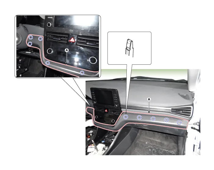
[Crash pad center garnish]
|

| 1. | Using a remover and remove the crash pad side cover [RH] (A).
|

| 2. | Remove the crash pad lower panel. (Refer to Crash Pad - "Crash Pad Lower Panel") |
| 3. | Loosen the mounting screw and remove the crash pad center garnish (A).
|
| 4. | Press the lock pin and separate the in-car sensor connector (A).
|
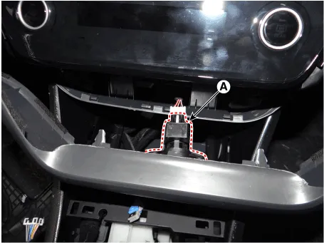
| 5. | To install, reverse the removal procedure.
|

Crash pad garnish [RH]
|
| 1. | Using a remover and remove the crash pad side cover [RH] (A).
|
| 2. | Loosen the mounting screw and remove the crash pad garnish [RH] (A).
|
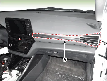
| 3. | To install, reverse the removal procedure.
|
Component Location 1. Crash pad center garnish2. Crash pad garnish [RH]
Component Location 1. Steering column shroud lower panel2. Steering column shroud upper panel
Other information:
Hyundai Ioniq (AE) 2017-2022 Service & Repair Manual: Components and components location
C
Hyundai Ioniq (AE) 2017-2022 Service & Repair Manual: Parking Distance Warning (PDW) Sensor. Repair procedures
Removal1.Disconnect the negative (-) battery terminal.2.Remove the front / rear bumper cover.(Refer to Body - "Front Bumper Cover")(Refer to Body - "Rear Bumper Cover")3.Disconnect the connector (A) from the parking assist sensor.4.Remove the sensor (A) by pulling out both ends of the sensor holder.
Categories
- Manuals Home
- Hyundai Ioniq Owners Manual
- Hyundai Ioniq Service Manual
- How to Connect Portable Charger (ICCB: In-Cable Control Box)
- Hybrid Control System
- Theft-alarm System
- New on site
- Most important about car

Copyright © 2026 www.hioniqae.com - 0.0165