
Hyundai Ioniq (AE): Cylinder Head Assembly / Cylinder Head Cover. Components and components location
Hyundai Ioniq (AE) 2017-2022 Service & Repair Manual / Engine Mechanical System / Cylinder Head Assembly / Cylinder Head Cover. Components and components location
| Components |
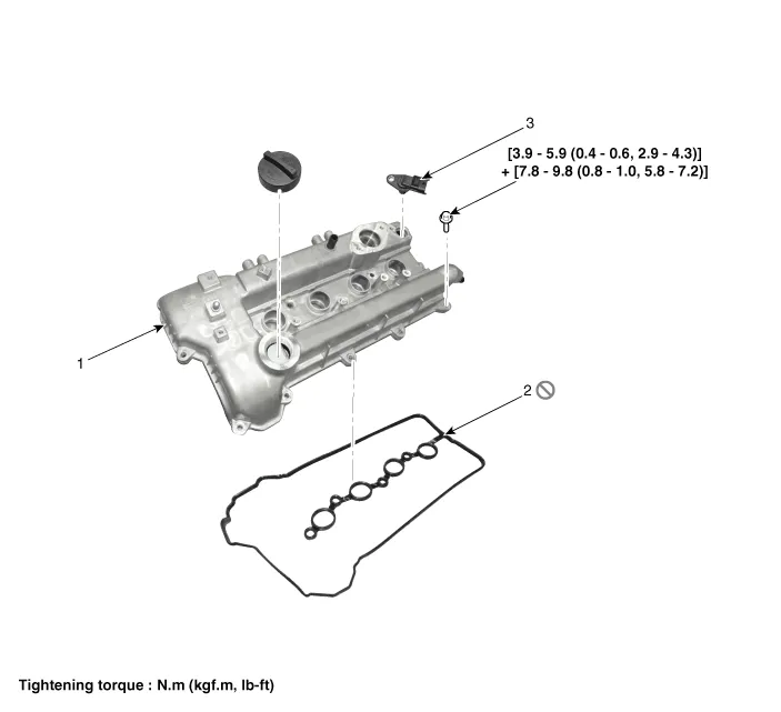
| 1. Cylinder head cover 2. Cylider head cover gasket | 3. Camshaft position sensor |
Components1. Camshaft bearing cap2. Front camshaft bearing cap3. Exhaust camshaft4. Intake camshaft5. Exhaust CVVT assembly6. Intake CVVT assembly7. Cylinder head assembly8.
Removal • Use fender covers to avoid damaging painted surfaces. • To avoid damage, unplug the wiring connectors carefully while holding the connector portion.
Other information:
Hyundai Ioniq (AE) 2017-2022 Service & Repair Manual: Auto Defoging Actuator. Components and components location
C
Hyundai Ioniq (AE) 2017-2022 Service & Repair Manual: Description and operation
Cruise ControlThe cruise control system is engaged by the cruise "ON/OFF" main switch located on right of steering wheel column. The system has the capability to cruise, coast, accelerate and resume speed.It also has a safety interrupt, engaged upon depressing brake or shifting select lever.
Categories
- Manuals Home
- Hyundai Ioniq Owners Manual
- Hyundai Ioniq Service Manual
- Hybrid Control System
- Troubleshooting
- Description and operation
- New on site
- Most important about car

Copyright © 2026 www.hioniqae.com - 0.0172