Hyundai Ioniq (AE): Cylinder Head Assembly / Cylinder Head Cover. Repair procedures
| Removal |
|

|

| 1. | Disconnect the battery negative terminal. |
| 2. | Remove the air cleaner assembly. (Refer to Intake and Exhaust System - "Air Cleaner") |
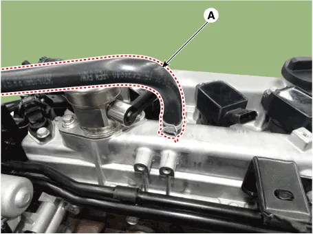
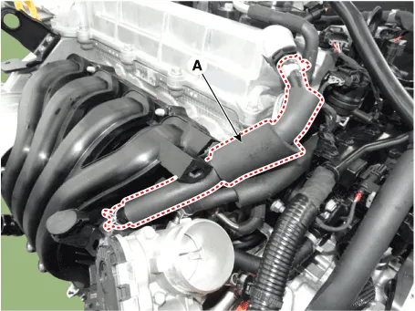
| 3. | Disconnect the breather hose (A).
|
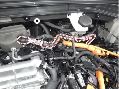
| 4. | Disconnect the fuel hose (A).
|
| 5. | Disconnect the reservoir tank coolant hose. (Refer to Cooling System - "Reservoir Tank") |
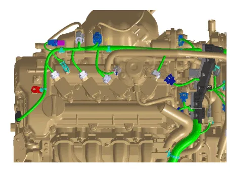
| 6. | Disconnect the wiring connectors and harness clamps and remove the connector brackets around the cylinder head cover.
|
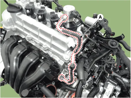
| 7. | Remove the reservoir tank coolant pipe (A).
|
| 8. | Disconnect the positive crankcase ventilation (PCV) hose (A).
|
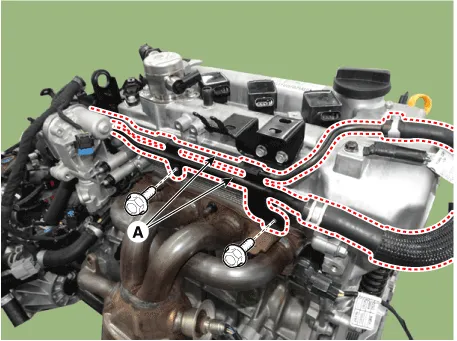
| 9. | Remove the high pressure fuel pipe (A).
|
| 10. | Remove the high pressure fuel pump. (Refer to Engine Control / Fuel System - "High Pressure Fuel Pump") |
| 11. | Remove the ignition coils. (Refer to Engine Electrical System - "Ignition Coil") |
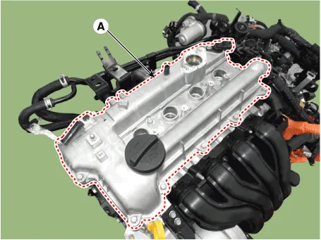
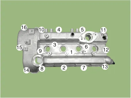
| 12. | Remove the cylinder head cover (A).
|
| Installation |
| 1. | Install the cylinder head cover.
|
| 2. | Install the other parts in the reverse order of removal. |
Components1. Cylinder head cover2. Cylider head cover gasket3. Camshaft position sensor
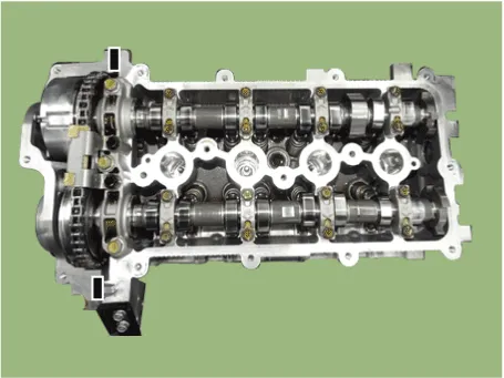
Components1. Camshaft bearing cap2. Front camshaft bearing cap3. Exhaust camshaft4. Intake camshaft5. Exhaust CVVT assembly6. Intake CVVT assembly
Other information:
Hyundai Ioniq (AE) 2017-2022 Service & Repair Manual: Duct Sensor. Repair procedures
Inspection1.Check that the voltage values of No. 1, 2 duct sensors change1. Sensor (+ 5V)2. Sensor groundSpecification Ambient temperature [°C (°F)] Resistance (kΩ) Voltage (V) 50 (122)1.
Hyundai Ioniq (AE) 2017-2022 Service & Repair Manual: PTC Heater. Description and operation
DescriptionThe PTC (Positive Temperature Coefficient) heater is installed at the exit or the backside of the heater core.The PTC heater is an electric heater using a PTC element as an auxiliary heating device that supplements deficiency of interior heat source in highly effective hybrid engine.
Categories
- Manuals Home
- Hyundai Ioniq Owners Manual
- Hyundai Ioniq Service Manual
- General Information
- Jump starting procedure
- Theft-alarm System
- New on site
- Most important about car
