Hyundai Ioniq (AE): Cylinder Head Assembly / Cylinder Head. Repair procedures
| Removal |
|

|

|

| 1. | Shut off the High Voltage circuit. (Refer to General Information - "High Voltage Shutoff Procedure") |
| 2. | Disconnect the battery negative terminal. |
| 3. | Remove the air cleaner assembly. (Refer to Intake and Exhaust System - "Air Cleaner") |
| 4. | Remove the RH front wheel. (Refer to Suspension System - "Wheel") |
| 5. | Remove the engine room under cover. (Refer to Engine and Transaxle Assembly - "Engine Room Under Cover") |
| 6. | Loosen the drain plug, and drain the engine coolant. Remove the reservoir cap to help drain the coolant faster. (Refer to Cooling System - "Coolant") |
| 7. | Loosen the drain plug, and drain the inverter coolant. Remove the reservoir cap to help drain the coolant faster. (Refer to Hybrid Motor System - "Coolant") |
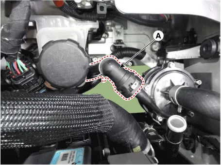
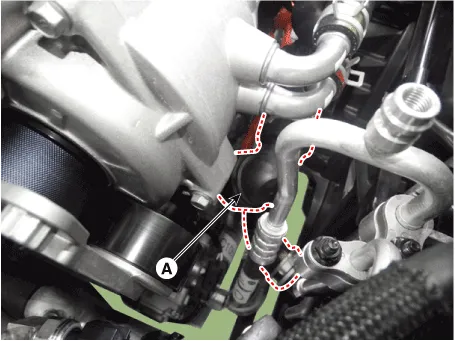
| 8. | Disconnect the electric water pump (EWP) coolant hose (A).
|
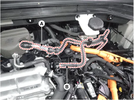
| 9. | Disconnect the fuel hose (A) and the purge control solenoid valve (PCSV) hose (B).
|
| 10. | Disconnect the wiring connectors and harness clamps and remove the connector brackets around the cylinder head.
|
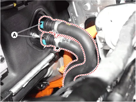
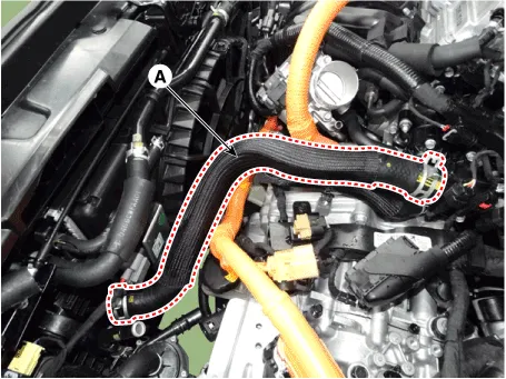
| 11. | Disconnect the heater hoses (A).
|
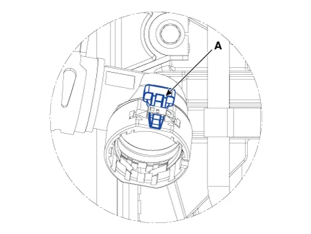
| 12. | Disconnect the radiator upper hose (A).
|
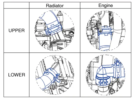
| 13. | Disconnect the radiator lower hose (A).
|
| 14. | Remove the water temperature control assembly. (Refer to Cooling System - "Water Temperature Control Assembly") |
| 15. | Remove the cylinder head cover. (Refer to Cylinder Head Assembly - "Cylinder Head Cover") |
| 16. | Remove the intake manifold. (Refer to Intake and Exhaust System - "Intake Manifold") |
| 17. | Remove the exhaust manifold. (Refer to Intake and Exhaust System - "Exhaust Manifold") |
| 18. | Remove the timing chain. (Refer to Timing System - "Timing Chain") |
| 19. | Remove the heater pipe. (Refer to Cooling System - "Water Temperature Control Assembly") |
| 20. | Remove the electric EGR (EEGR) control valve. (Refer to Engine Control / Fuel System - "Electric EGR Control Valve (EEGR)") |
| 21. | Remove the CVVT & camshaft. (Refer to Cylinder Head Assembly - "CVVT & Camshaft") |
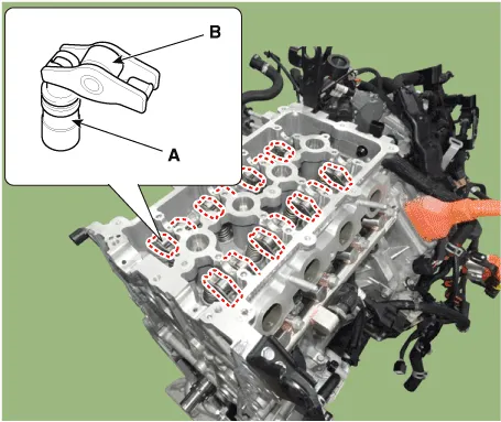
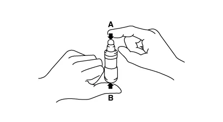
| 22. | Remove the hydraulic lash adjuster (HLA) (A) and the swing arm (B).
|
| 23. | Remove the spark plugs. (Refer to Engine Electrical System - "Spark Plug") |
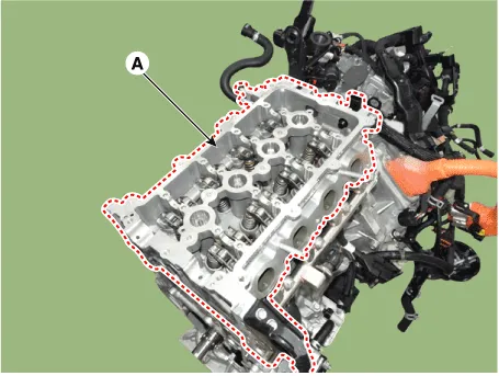
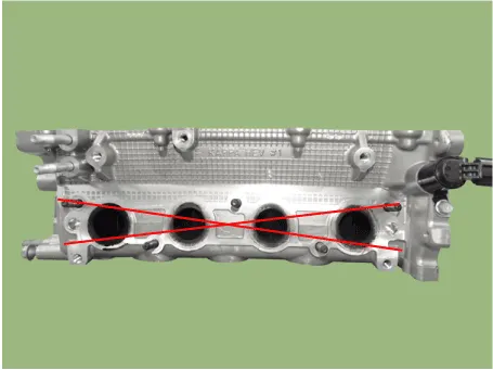
| 24. | Remove the cylinder head.
|
| Disassembly |
|
| 1. | Remove the valves.
|
| Inspection |
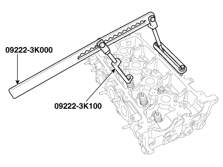
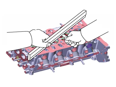
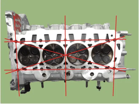
| 1. | Inspect for flatness. Using a precision straight edge and feeler gauge, measure the surface contacting cylinder block and the manifolds for warpage.
|
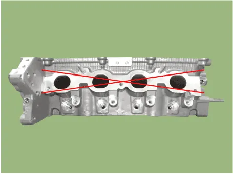
| 2. | Inspect for cracks. Check the combustion chamber, intake ports, exhaust ports and cylinder block surface for cracks. If cracked, replace the cylinder head. |
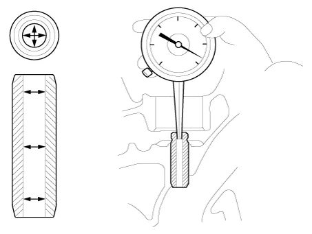
| 1. | Inspect valve stems and valve guides.
|
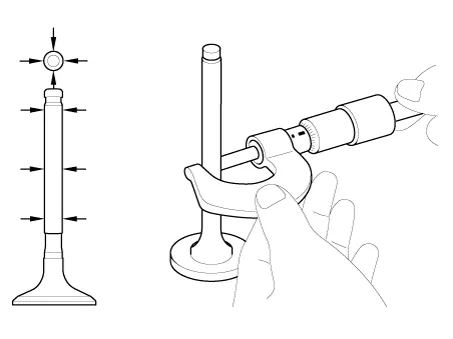
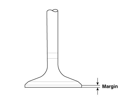
| 2. | Inspect valves.
|
| 3. | Inspect valve seats.
|
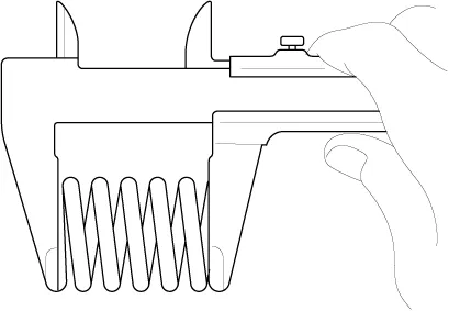
| 4. | Inspect valve springs.
|
| Problem | Possible cause | Action | |||||
| 1. Temporary noise when starting a cold engine | Normal | This noise will disappear after the oil in the engine reaches the normal pressure. | |||||
| 2. Continuous noise when the engine is started after parking more than 48 hours | Oil leakage of the high pressure chamber on the HLA, allowing air to get in | Noise will disappear within 15 minutes when engine runs at 2000-3000 rpm. If it doesn’t disappear, refer to step 7 below. | |||||
| 3. Continuous noise when the engine is first started after rebuilding cylinder head | Insufficient oil in cylinder head oil gallery | ||||||
| 4. Continuous noise when the engine is started after excessively cranking the engine by the starter motor or band |
| ||||||
| 5. Continuous noise when the engine is running after changing the HLA |
| ||||||
| 6. Continuous noise during idle after high engine speed | Engine oil level too high or too low |
| |||||
| Excessive amount of air in the oil at high engine speed | Check oil supply system. | ||||||
| Deteriorated oil | Check oil quality. If deteriorated, replace with specified type. | ||||||
| 7. Noise continues for more than 15 minutes | Low oil pressure | Check oil pressure and oil supply system of each part of engine. | |||||
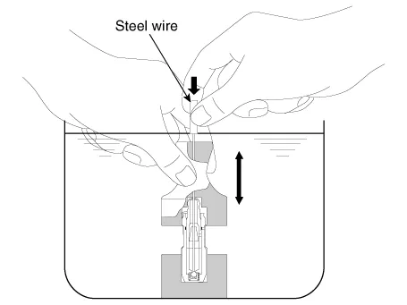
| Faulty HLA | Remove the cylinder head cover and press HLA down by hand. If it moves, replace the HLA. |
| Reassembly |
|
| 1. | Install the valves.
|


| Installation |
|
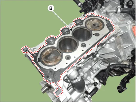
| 1. | Install the cylinder head gasket.
|

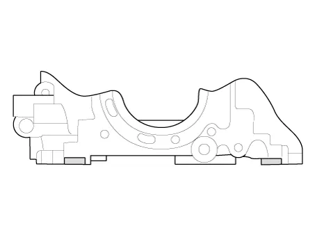
| 2. | Place the cylinder head (A) carefully to protect damage to the head gasket during installation.
|
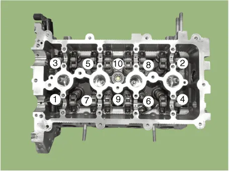
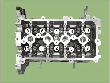
| 3. | Install the cylinder head bolts with washers. Using SST (09221-4A000), install and tighten the 10 cylinder head bolts, in several passes, in the sequence as shown.
|

| 4. | Install the spark plugs. (Refer to Engine Electrical System - "Spark Plug") |
| 5. | Install the hydraulic lash adjuster (HLA) (A) and the swing arm (B).
|
| 6. | Install the other parts reverse order of removal. |
| 7. | Connect the High Voltage circuit. (Refer to General Information - "High Voltage Shutoff Procedure")
|
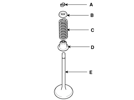
Components1. Cylinder head assembly2. Cylinder head gasket3. Retainer lock4. Retainer5. Valve spring6. Valve stem seal7. Valve8. Swing arm9. Hydraulic lash adjuster (HLA)
Other information:
Hyundai Ioniq (AE) 2017-2022 Service & Repair Manual: emperature Control Actuator. Description and operation
DescriptionThe temperature control actuator is located at the heater unit. It regulates the temperature by the procedure as follows. The signal from the control unit adjusts the position of the temperature door by operating the temperature switch. Then the temperature will be regulated by the hot/cold air ratio decided by the position of the temper
Hyundai Ioniq (AE) 2017-2022 Service & Repair Manual: Rear Corner Safety ON/OFF Switch. Repair procedures
Inspection1.Disconnect the negative (-) battery terminal.2.Remove the crash pad lower panel.(Refer to Body - "Crash Pad Lower Panel")3.Remove the lower crash pad switch assembly (A) after disengaging the mounting clip.4.Remove the rheostat switch connector (A).
Categories
- Manuals Home
- Hyundai Ioniq Owners Manual
- Hyundai Ioniq Service Manual
- Engine Control/Fuel System
- Jump Starting
- Body (Interior and Exterior)
- New on site
- Most important about car
