Hyundai Ioniq (AE): Dual Clutch Transmission Assembly / DCT (Dual Clutch Transmission). Repair procedures
| Removal |
|

|

| 1. | Shut off the High Voltage circuit. (Refer to General Information - "High Voltage Shutoff Procedure") |
| 2. | Remove the engine room under cover. (Refer to Engine And Transaxle Assembly - "Engine Room Under Cover") |
| 3. | Loosen the drain plug, and drain the inverter coolant. Remove the reservoir cap to help drain the coolant faster. (Refer to Hybrid Motor System - "Coolant") |
| 4. | Remove the HPCU (Hybrid Power Control Unit). (Refer to Hybrid Control System - "Hybrid Power Control Unit (HPCU)") |
| 5. | Remove the ECM (Engine Control Module) and TCM (Transmssion Control Module). (Refer to Engine Control/Fuel System - "Engine Control Module (ECM)") (Refer to Dual Clutch Control System - "DCT Control Module (TCM)") |
| 6. | Remove the HPCU (Hybrid Power Control Unit) tray. (Refer to Hybrid Control System - "Hybrid Power Control Unit (HPCU)") |
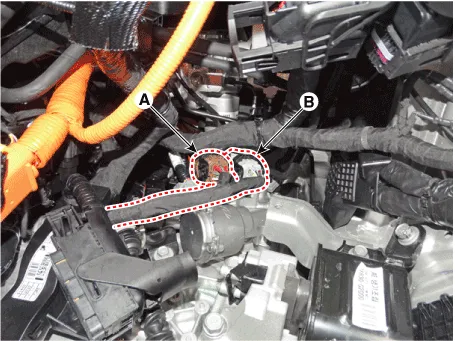
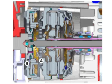
| 7. | Disconnect the gear actuator motor connector (A) and solenoid connector (B).
|
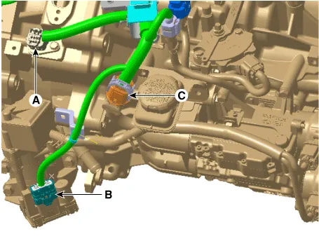
| 8. | Disconnect the hybrid motor connector (A) and engine clutch actuator connector (B). |
| 9. | Disconnect the DCT clutch actuator connector (C).
|
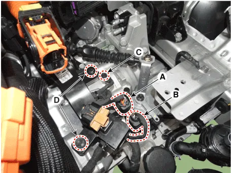
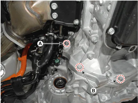
| 10. | Disconnect the inhibitor switch connector (A) and input shaft speed sensor connector (B). |
| 11. | Remove the ground bolt (C) and wiring bracket bolt (D).
|
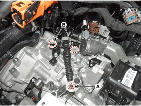
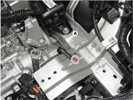
| 12. | Remove the nut (A) and shift cable bracket bolt (B-2ea).
|
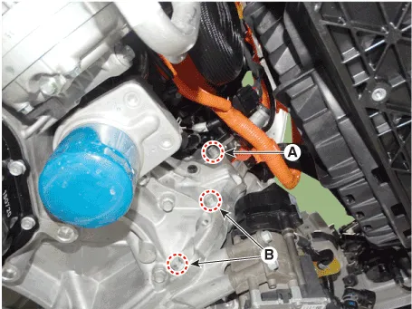
| 13. | Remove the ground bolts (A).
|
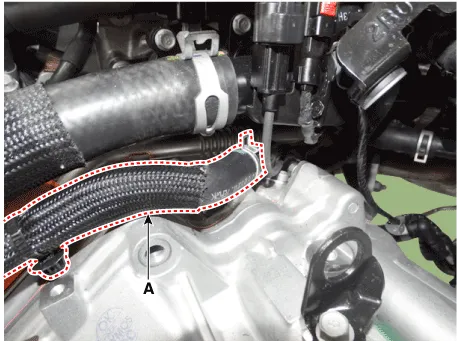
| 14. | Remove the hybrid motor cooling hose (A).
|
| 15. | Remove the hybrid motor upper mounting bolt (A-3ea).
|
| 16. | Assemble the engine support fixture (beam No.: 09200-38001 or 09200-3N000, supporter No.: 09200-2S000). (Refer to Special Service Tools - "Engine Support Fixture Assembly Drawing") |
| 17. | Using the engine support fixture(A), hold the engine and transaxle assembly safely.
|

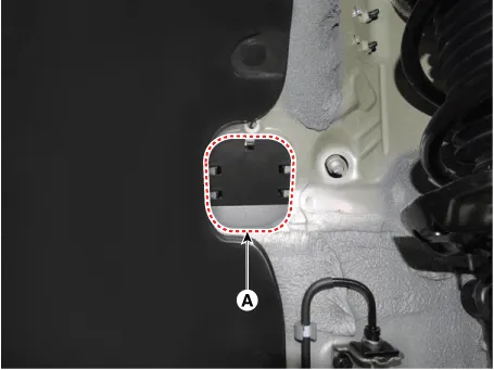
| 18. | Remove the dust cover (A).
|
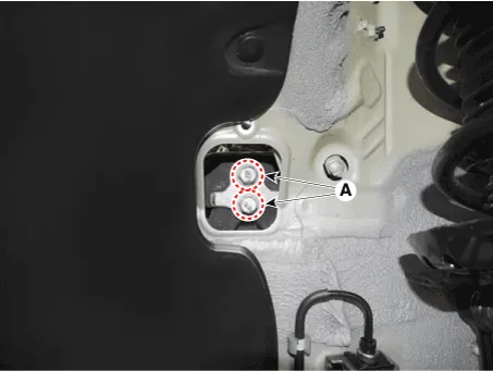
| 19. | Remove the transmission support bracket mounting bolt (A-2ea).
|
| 20. | Remove the transmission support bracket (A).
|
| 21. | Remove the sub frame. (Refer to Suspension System - "Sub Frame") |
| 22. | Remove the front drive shaft assembly. (Refer to Driveshaft and Axle - "Front Driveshaft") |
| 23. | Remove the AWEP (Auxiliary Electronic water pump). (Refer to Heating, Ventilation and Air Conditioning - "AWEP (Auxiliary Electronic water pump)") |
| 24. | Remove the crankshaft position sensor. (Engine Control / Fuel System - "Crankshaft Position Sensor (CKPS)") |
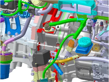
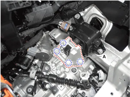
| 25. | Remove the roll rod support bracket (A).
|
| 26. | Support the hybrid motor and transmission safely by using the jack. |
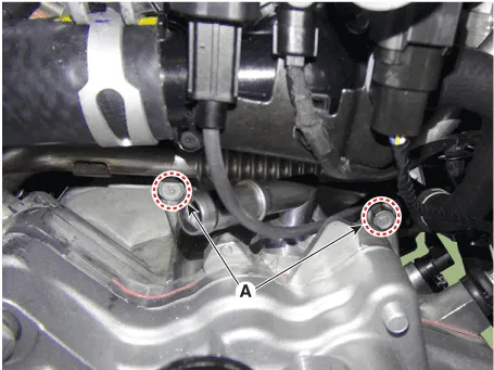
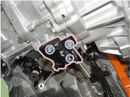
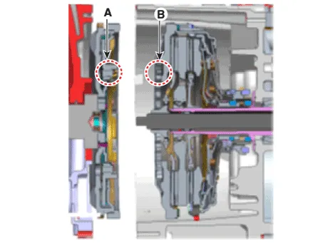
| 27. | Remove the hybird motor lower mounting bolts (A, B).
|
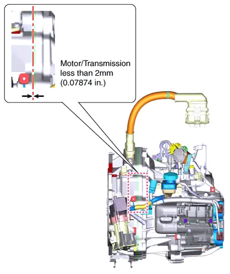
| 28. | After separating the hybrid motor and transmission from the engine, remove the transmission by lowering the jack slowly.
|

| 29. | Remove the hybrid motor assembly from the dual clutch transmission. |
| Installation |
| 1. | Install in the reverse order of removal.
|
| 2. | Observe each separate procedure below for reinstallation or replacement with a new dual clutch transmission. |
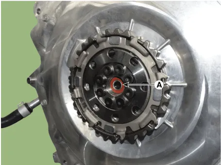
| 1. | If the differential oil seal is damaged and oil is leaking, replace the oil seal with a new one. When installing a new oil seal, use the special tool (09430-C1190, 09231-H1100). |
| 2. | After installing the DCT, check the oil level after refilling the DCT with oil. (Refer to Dual Clutch Transmission System - "Transmission Gear oil") |
| 3. | Bleed air from the hybrid motor cooling system using GDS. (Refer to Hybrid Motor System- "Coolant") |
| 4. | Clear the diagnostic trouble codes (DTC) using the KDS/GDS. Disconnecting the battery negative terminal will not clear the DTCs. Clear the DTCs using the KDS/GDS at all times. |
| 1. | After replacing the new DCT, it need not oil refill & level check procedure because oil is already filled with specified quantity inside new DCT. |
| 2. | Clear the diagnostic trouble codes (DTC) using the KDS/GDS. Disconnecting the battery negative terminal will not clear the DTCs. Clear the DTCs using the KDS/GDS at all times. |
| 3. | Bleed air from the hybrid motor cooling system using the GDS. (Refer to Hybrid Motor System- "Coolant") |
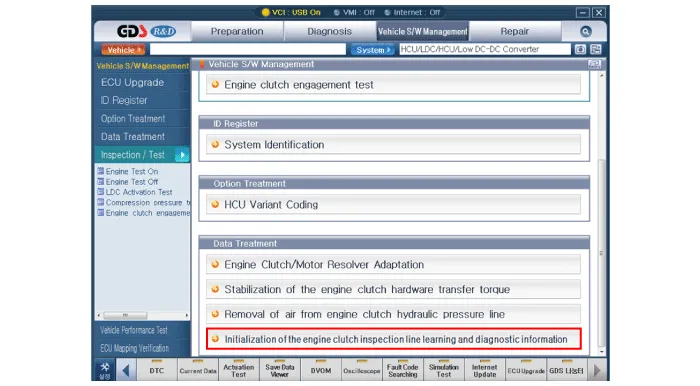
| 4. | Perform initialization of the engine clutch inspection line learning and diagnostic information using the GDS.
|
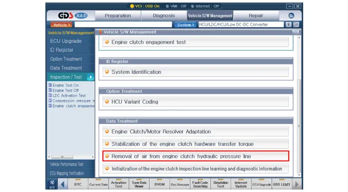
| 5. | Perform of the removal of air from engine clutch hydraulic pressure line using the GDS.
|
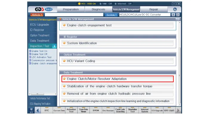
| 6. | Perform of the engine clutch/motor resolver adaptation using the GDS.
|
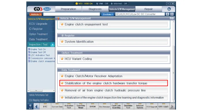
| 7. | Perform of the stabilization of the engine clutch hardware transfer torque using the GDS.
|
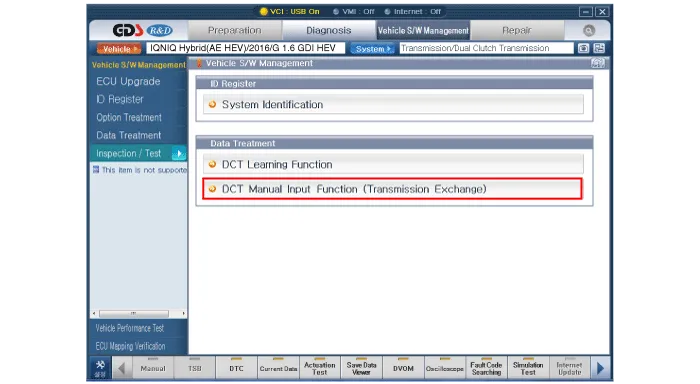
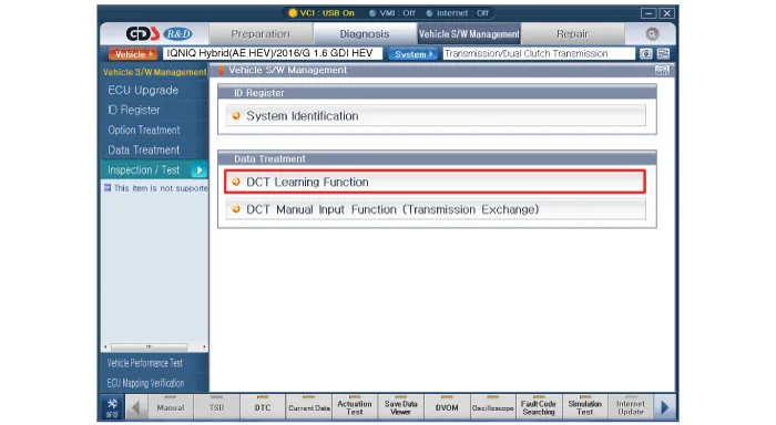
| 8. | Perform clutch characteristics input procedure using the GDS. (One of two procedures must be performed.)
|
Components (1)1. Dual clutch transmission assembly2. Hybrid motor assembly3. Gear actuator4. Clutch actuator5. Engine clutch actuator6. Reserver7. Dust cover8.
General Information1.Check & Change intervals Check & Replenishment Change Capacity Oil specification Normal Use Severe Use No checkNo service required120000 km( 80000 miles)1.
Other information:
Hyundai Ioniq (AE) 2017-2022 Service & Repair Manual: Evaporator Temperature Sensor. Description and operation
DescriptionThe evaporator temperature sensor will detect the evaporator core temperature and interrupt compressor relay power in order to prevent evaporator from freezing by excessive cooling. The evaporator temperature sensor has the Negative Temperature Coefficient (NTC).
Hyundai Ioniq (AE) 2017-2022 Service & Repair Manual: Repair procedures
Replacement1.Remove the battery (-) terminal.2.Remove the engine room under cover.(Refer to Engine Mechanical System - "Engine Room Under Cover")3.Remove the heater hose (A) and AEWP hose (B).4.Disconnect the lock pin to remove the heater hose pump connector (A).
Categories
- Manuals Home
- Hyundai Ioniq Owners Manual
- Hyundai Ioniq Service Manual
- Suspension System
- Theft-alarm System
- Jump starting procedure
- New on site
- Most important about car
