
Hyundai Ioniq (AE): Emergency Call System / Emergency Call (eCall) Button. Repair procedures
Hyundai Ioniq (AE) 2017-2022 Service & Repair Manual / Body Electrical System / Emergency Call System / Emergency Call (eCall) Button. Repair procedures
| Removal |
| 1. | Disconnect the negative (-) battery terminal. |
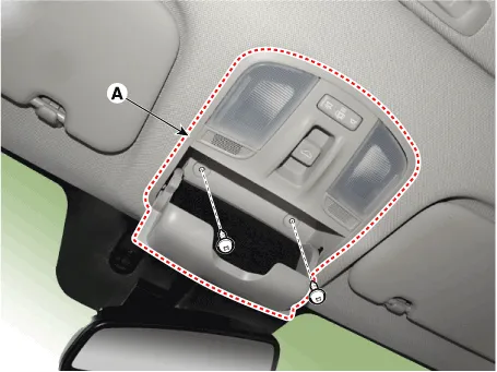
| 2. | separate the overhead console (A) from the roof trim after loosening the mounting screws.
|
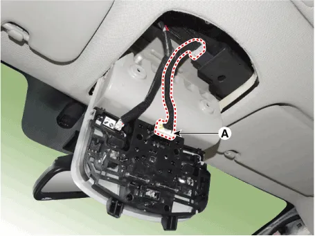
| 3. | Remove the overhead console (A) after disconnecting the connector (A)
|
| Installation |
| 1. | Install the overhead console assembly after connecting the connector. |
| 2. | Connect the negative (-) battery terminal. |
SCHEMATIC DIAGRAM
ComponentsRADIO+GNSS+eCallRADIO+GNSS+DAB+eCall
Other information:
Hyundai Ioniq (AE) 2017-2022 Service & Repair Manual: Front Radar Unit. Repair procedures
Removal1.Remove the front bumper.(Refer to Body - "Front Bumper")2.Disconnect the smart cruise control unit connector (A).3.Remove the smart cruise control nuit assembly (B) from thevehicle after loosening mounting bolts.Installation1.Install in the reverse order of removal.
Hyundai Ioniq (AE) 2017-2022 Service & Repair Manual: Parking Distance Warning (PDW) ON/OFF Switch. Repair procedures
Removal • Put on gloves to prevent hand injuries. • When removing with a flat-tip screwdriver or remover, wrap protective tape around the tools to prevent damage to components.
Categories
- Manuals Home
- Hyundai Ioniq Owners Manual
- Hyundai Ioniq Service Manual
- Engine Control/Fuel System
- DCT(Dual Clutch Transmission) System
- Transmission Gear Oil. Repair procedures
- New on site
- Most important about car

Copyright © 2026 www.hioniqae.com - 0.0164