Hyundai Ioniq (AE): Emergency Call System / Emergency Call (eCall) Unit. Repair procedures
Hyundai Ioniq (AE) 2017-2022 Service & Repair Manual / Body Electrical System / Emergency Call System / Emergency Call (eCall) Unit. Repair procedures
| Removal |
You must make sure turn RED LED ON if you do any of the following.
|

| 1. | Disconnect the negative (-) battery terminal. |
| 2. | Remove the floor console assembly. (Refer to Body - "Floor Console Assembly") |
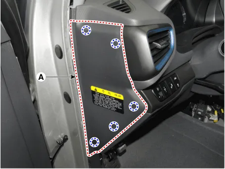
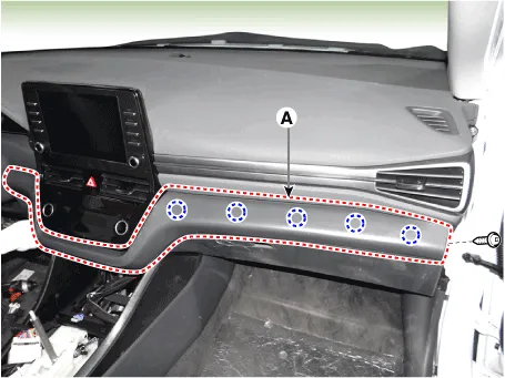
| 3. | Remove the crash pad side cover [LH] (A) by using a remover.
|
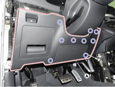
| 4. | Loosen the mounting screws and remove the crash pad lower panel (A).
|
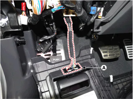
| 5. | Press the lock pin and separate the diagnosis connector (A)
|
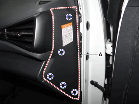
| 6. | Remove the crash pad side cover [RH] (A) by using a remover.
|
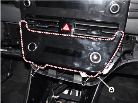
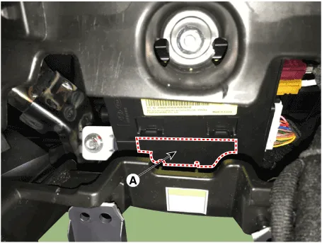
| 7. | Loosen the mounting screw and remove the crash pad center garnish (A).
|
| 8. | Loosen the mounting screws and remove the A/C & heater controller unit (A).
|
| 9. | Press the lock pin and separate the A/C & heater controller unit connectors (A).
|
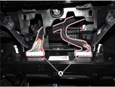
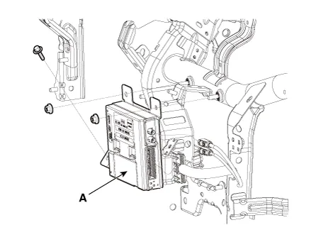
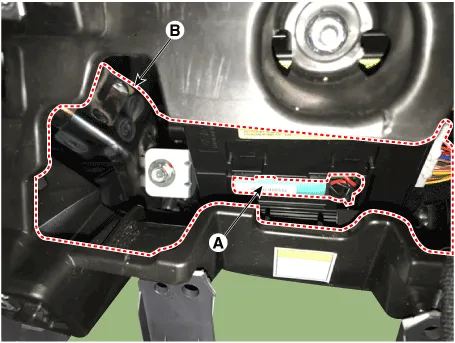
| 10. | Disconnect the ecall unit connector (A) and antenna connectors (B)
|
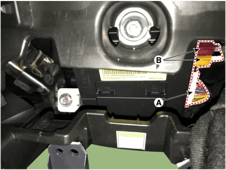
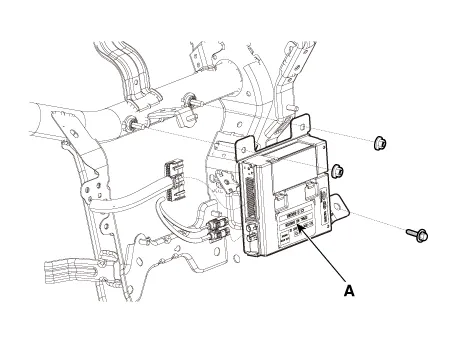
| 11. | Loosen the mounting bolts and nuts and remove the e-call unit (A) towards the console. [LHD]
[RHD]
|
| Replacement |
e-Call Unit Back Up Battery (BUB)
[LHD]
| 1. | Disconnect the negative (-) battery terminal. |
| 2. | Remove the eCall Unit. |
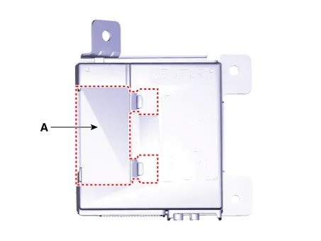
| 3. | If it is necessary to replace the back-up battery, remove the back-up battery cover (A).
|
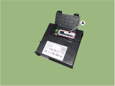
| 4. | Replace the back-up battery (A).
|
[RHD]
| 1. | Disconnect the negative (-) battery terminal. |
| 2. | Remove the crash pad side cover [RH] (A) by using a remover.
|
| 3. | Loosen the mounting screw and remove the crash pad center garnish (A).
|
| 4. | Loosen the mounting screws and remove the A/C & heater controller unit (A).
|
| 5. | Press the lock pin and separate the A/C & heater controller unit connectors (A).
|
| 6. | Disconnect the ecall unit back battery (BUB) service cover (A).
|
| 7. | Replace the back-up battery (A) through service space (B).
|
| Installation |
If RED LED is on, check the eCall system with the diagnostic tools.
|
eCall Unit
| 1. | Install the eCall unit. |
| 2. | Install the main crash pad assembly. |
| 3. | Connect the negative (-) battery terminal. |
| 4. | Perform the "eCall Parameter Download" (Refer to Inspection - " Inspection with Diagnostic Tools") |
| Inspection |
Inspecting Back-Up Battery
Back-up battery (BUB) embedded in the eCall system has a finite lifespan and using it for a long time may decrease its charging/discharging performance.
The back-up battery guarantees the operation of the eCall system when the vehicle battery cannot be used due to an accident. Be sure to inspect the back-up battery if the red LED turns on and replace it if necessary.
|
|

|

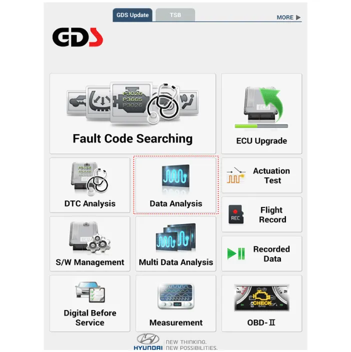
Inspection with Diagnostic Tools
In the eCall system, failure can be quickly diagnosed by using the vehicle diagnostic system.
The diagnostic system provides the following information.
| 1) | Self diagnosis : Checking failure and code number (DTC) |
| 2) | Current data : Checking the system input/output data state |
| 1. | Select the "Car Model" and the "eCall System" to be checked in order to check the vehicle with the tester. |
| 2. | To inquire the cause of trouble for each module by self diagnosis, select 'Diagnostic Trouble Code'.
|

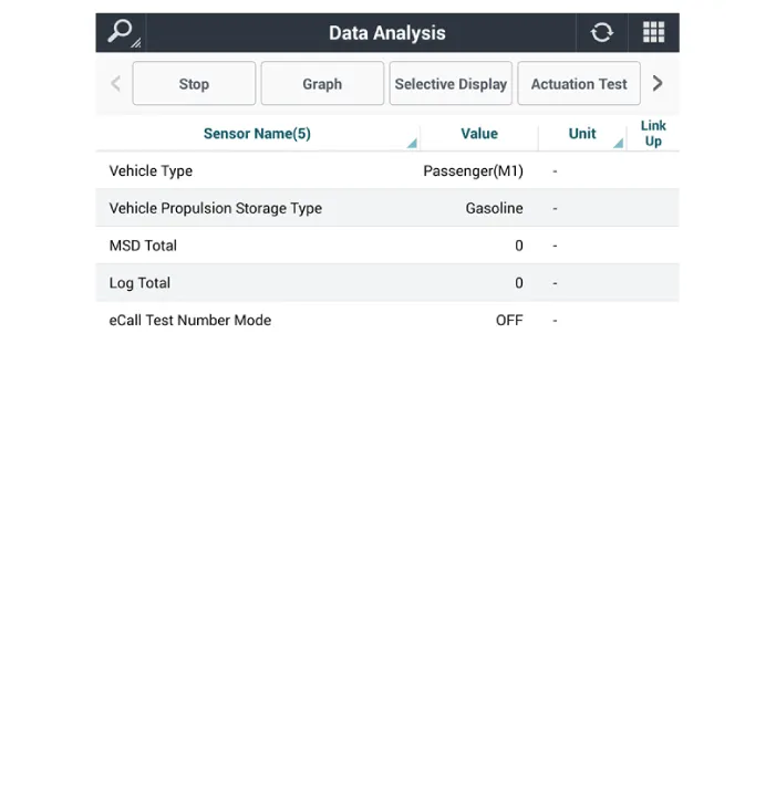
| 3. | Select the 'Current Data' menu to check the current state of the input/output data.
|
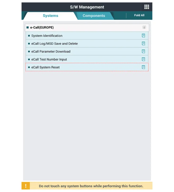
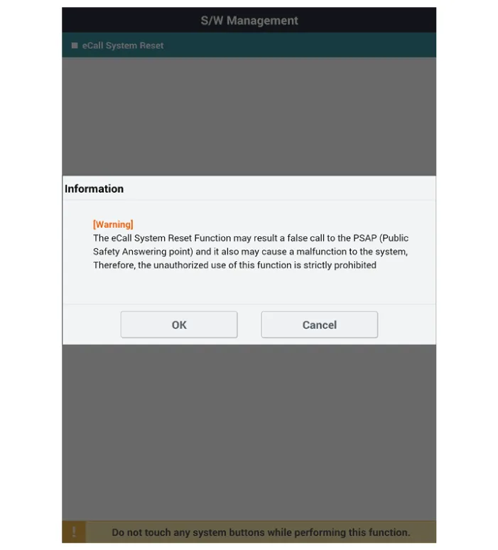
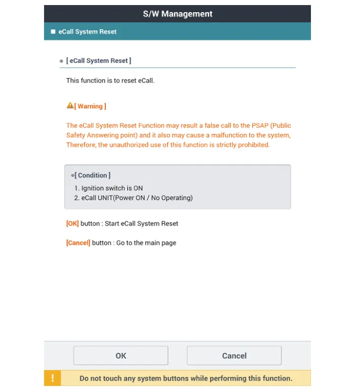
eCall System Reset
The eCall System Reset function is to reset when eCall is locked or stopped.
|
| 1. | Turn the ignition switch OFF. |
| 2. | Connect the diagnostic tools. |
| 3. | Turn the ignition switch ON without the engine running. |
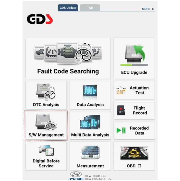
| 4. | Select the "Car Model" and "S/W Management".
|
| 5. | Select the "eCall System Reset"
|
| 6. | Follow the screen instructions to perform the "eCall System Reset".
|
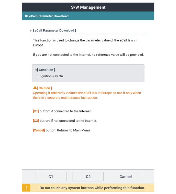
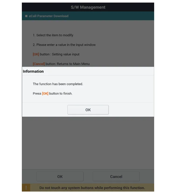
eCall Parameter Download
eCall Parameter Download is used to change the parameter value of the eCall law in Europe.
| 1. | Turn the ignition switch OFF. |
| 2. | Connect the diagnostic tools. |
| 3. | Turn the ignition switch ON without the engine running. |
| 4. | Select the "Car Model" and "S/W Management".
|
| 5. | Select the "eCall Parameter Download"
|

| 6. | Follow the screen instructions to perform the "eCall Parameter Download".
|
SCHEMATIC DIAGRAM
Other information:
Hyundai Ioniq (AE) 2017-2022 Service & Repair Manual: Evaporator Temperature Sensor. Repair procedures
Inspection1.Turn the ignition switch OFF.2.Disconnect the evaporator temperature sensor connector.3.Measure the resistance between terminal "+" and "-" of the evaporator temperature sensor.Specification Evaporator core temperature [°C (°F)] Resistance [KΩ]
Hyundai Ioniq (AE) 2017-2022 Service & Repair Manual: PTC Heater. Description and operation
DescriptionThe PTC (Positive Temperature Coefficient) heater is installed at the exit or the backside of the heater core.The PTC heater is an electric heater using a PTC element as an auxiliary heating device that supplements deficiency of interior heat source in highly effective hybrid engine.
Categories
- Manuals Home
- Hyundai Ioniq Owners Manual
- Hyundai Ioniq Service Manual
- Transmission Gear Oil. Repair procedures
- DCT(Dual Clutch Transmission) System
- How to Connect Portable Charger (ICCB: In-Cable Control Box)
- New on site
- Most important about car

Copyright © 2026 www.hioniqae.com - 0.0153