Hyundai Ioniq (AE): Intake and Exhaust System / Exhaust Manifold. Repair procedures
Hyundai Ioniq (AE) 2017-2022 Service & Repair Manual / Engine Mechanical System / Intake and Exhaust System / Exhaust Manifold. Repair procedures
| Removal and Installation |
| 1. | Disconnect the battery negative terminal. |
| 2. | Remove the air cleaner assembly. (Refer to Intake and Exhaust System - "Air Cleaner") |
| 3. | Remove the engine room under cover. (Refer to Engine and Transaxle Assembly - "Engine Room Under Cover") |
| 4. | Remove the front muffler. (Refer to Intake and Exhaust System - "Muffler") |
| 5. | Remove the engine mounting support bracket. (Refer to Engine and Transaxle Assembly - "Engine Mounting") |
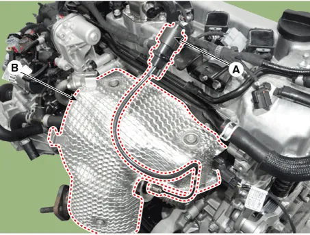
| 6. | Disconnect the oxygen sensor connector (A) from the connector bracket and then remove the heat protector (B).
|
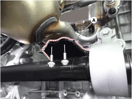
| 7. | Remove the exhaust manifold stay (A).
|
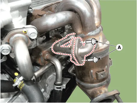
| 8. | Remove the EGR cooler pipe A bolts (A).
|
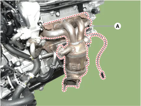
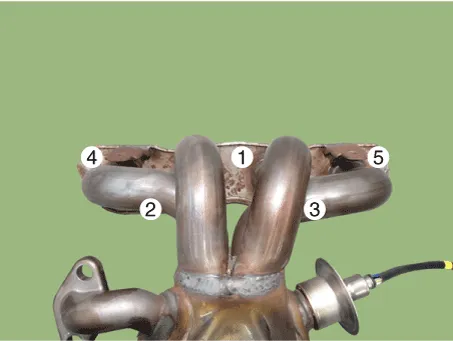
| 9. | Remove the exhaust manifold (A).
|
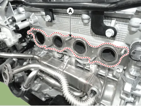
| 10. | Remove the exhaust manifold gasket (A).
|

| 11. | Install in the reverse order of removal. |
Components1. Exhaust manifold assembly2. Exhaust manifold gasket3. Exhaust manifold stay
Components1. EGR cooler pipe C2. Electric EGR (EEGR) control valve3. EGR cooler4. EGR cooler pipe A5. Gasket6. EGR cooler pipe B
Other information:
Hyundai Ioniq (AE) 2017-2022 Service & Repair Manual: Evaporator Temperature Sensor. Description and operation
DescriptionThe evaporator temperature sensor will detect the evaporator core temperature and interrupt compressor relay power in order to prevent evaporator from freezing by excessive cooling. The evaporator temperature sensor has the Negative Temperature Coefficient (NTC).
Hyundai Ioniq (AE) 2017-2022 Service & Repair Manual: Components and components location
C
Categories
- Manuals Home
- Hyundai Ioniq Owners Manual
- Hyundai Ioniq Service Manual
- Brake System
- If the 12 Volt Battery is Discharged (Hybrid Vehicle)
- Repair procedures
- New on site
- Most important about car

Copyright © 2026 www.hioniqae.com - 0.0212