Hyundai Ioniq (AE): Windshield Wiper/Washer / Front Washer Motor. Repair procedures
| Inspection |
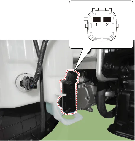
| 1. | With the washer motor connected to the reservoir tank, fill the reservoir tank with water.
|

| 2. | Connect positive (+) battery cables to terminal 2 and negative (-) battery cables to terminal 1 respectively. |
| 3. | Check that the motor operates normally and the washer motor runs and water sprays from the front nozzles. |
| 4. | If they are abnormal, replace the washer motor. [Front & Rear washer]
|
| 1. | Disconnect the negative (-) battery terminal. |
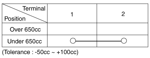
| 2. | Drain the washer fluid less than 650 cc. |
| 3. | Check for continuity between the No. 1 and No.2 terminal in each float position. There should be continuity when the float is down. There should be no continuity when the float is up. |
| 4. | If the continuity is not as specified, replace the washer fluid level switch
|
| Removal |
|

| 1. | Disconnect the negative (-) battery terminal. |
| 2. | Remove the right front wheel guard. (Refer to Body - "Front Wheel Guard") |
| 3. | Remove the engine room under cover (Refer to Engine Mechanical System - "Engine Room Under Cover") |
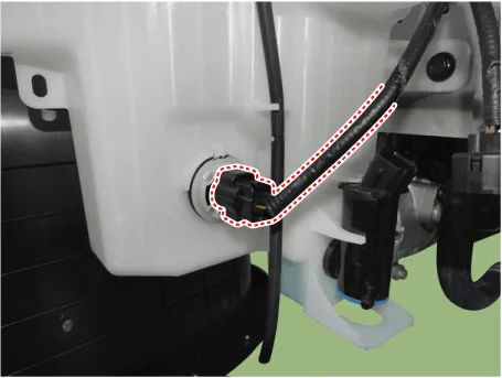
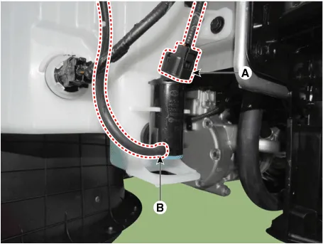
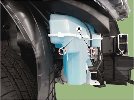
| 4. | Remove the washer hose (B) and disconnect the washer motor connector (A).
|
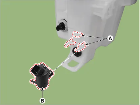
| 5. | Remove the reservoir washer inlet (A) after loosening the mounting bolt.
|
| 6. | Remove the washer motor (B) after disengaging the fixed hook (A).
|
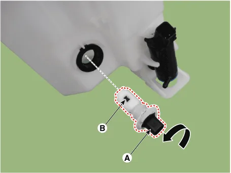
| 7. | Remove the level sensor switch (A).
|
| Installation |
| 1. | Install the washer reservoir.
|
| 2. | Install the washer motor. |
| 3. | Install the washer hose. |
| 4. | Connect the washer motor connector and level sensor connector. |
| 5. | Install the tire and wheel guide cover. (Refer to Body - "Front Wheel Guard") |
| 6. | Install the engine room under cover. (Refer to Engine Mechanical System - "Engine Room Under Cover") |
| 7. | Check the washer motor operation. |
Removal1.Disconnect the negative (-) battery terminal.2.If necessary, release the wiper blade fixing clip by pulling up and remove the wiper blade from the inside radius of wiper arm.
Components and Components Location
Other information:
Hyundai Ioniq (AE) 2017-2022 Service & Repair Manual: Repair procedures
Self Diagnosis1.Self-diagnosis process. • When operating the self-diagnostics, the below fault (self-diagnostics code) will blink at 0.5 seconds interval on the temperature display settings (driver's side only) and the remaining symbols are OFF .
Hyundai Ioniq (AE) 2017-2022 Service & Repair Manual: Description and operation
DescriptionThe smart cruise control system allows a driver to program the vehicle to control the speed and following distance by detecting the vehicle ahead without depressing the brake pedal and the accelerator pedal.1.Cruise speed control : The vehicle maintains the selected speed if there are not vehicles ahead.
Categories
- Manuals Home
- Hyundai Ioniq Owners Manual
- Hyundai Ioniq Service Manual
- Hybrid Vehicle Engine Compartment
- Jump Starting
- Transmission Gear Oil. Repair procedures
- New on site
- Most important about car
