Hyundai Ioniq (AE): Hybrid Control System / HPCU (Hybrid Power Control Unit). Repair procedures
| Removal |
|

| 1. | Shut off the high voltage circuit. (Refer to Hybrid Control System - "High Voltage Shutoff Procedure") |
| 2. | Remove the air cleaner assembly and air duct. (Refer to Engine Mechanical System - "Air Cleaner") |
| 3. | Remove the ECM & TCM bracket assembly. (Refer to Engine Control/Fuel System - "Engine Control Module") |
| 4. | Drain the coolant of hybrid motor cooling system. (Refer to Hybrid Motor Cooling System - "Coolant") |
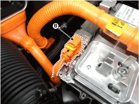
| 5. | Disconnect the motor power cable connector (A) and HSG power cable connector (B) after loosening the mounting bolts.
|
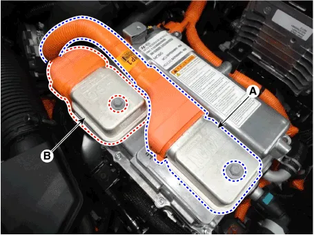
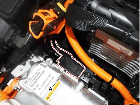
| 6. | Disconnect the power cable (A) and inverter power cable (B) from the HPCU.
|
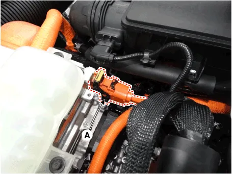

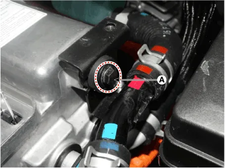
| 7. | Disconnect the HCU & inverter (MCU) connector (A).
|
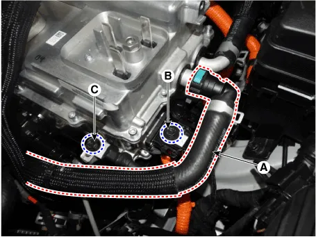
| 8. | Disconnect the coolant outlet hose & pipe after loosening the mounting bolt (A).
|
| 9. | Disconnect the coolant inlet hose quick-connector (A). |
| 10. | Remove the LDC power outlet cable mounting bolt (B) and ground cable bolt (C).
|
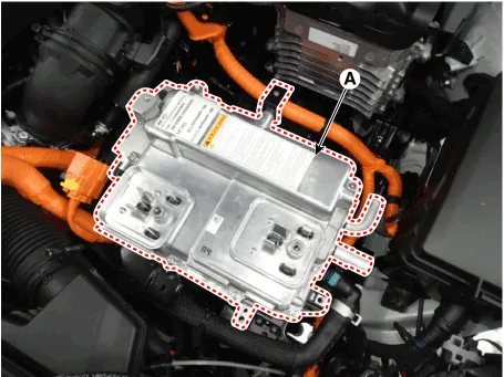
| 11. | Remove the HPCU (A) after loosening the mounting bolts.
|
| Installation |
|
| 1. | Install the HPCU in the reverse order of removal.
|
| 2. | Refill the hybrid motor cooling system coolant and perform air bleeding by using the GDS. (Refer to Hybrid Motor Cooling System - "Coolant")
|

| 1. | Turn the ignition switch OFF. |
| 2. | Connect the KDS / GDS to Data Link Connector (DLC). Turn the ignition switch ON. |
| 3. | Select "Vehicle, Model year, Engine, System". |
| 4. | Select "Vehicle S/W Management". |
| 5. | Select "HCU Variant Coding".
|

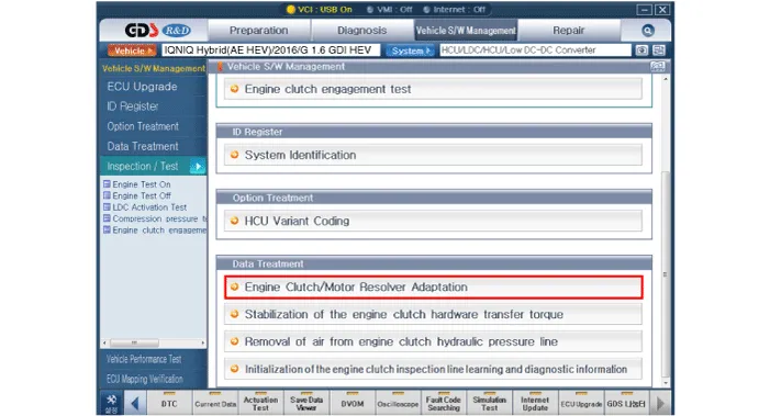
| 1. | Turn the ignition switch OFF. |
| 2. | Connect the KDS / GDS to Data Link Connector (DLC). Turn the ignition switch ON. |
| 3. | Select "Vehicle, Model year, Engine, System". |
| 4. | Select "Vehicle S/W Management". |
| 5. | Select "Engine clutch/motor resolver adaptation.".
|
Components1. Hybrid Control Unit (HCU)2. Inverter3. Low DC/DC Converter (LDC)4. Connector (тЖФ High Voltage Battery)5. Connector (тЖФ Motor)6. Connector (тЖФ HSG)7.
HCU Terminal and Input / Output SignalTerminal FunctionConnector [C133-S] Pin No Description Connected to 1HCU GroundChassis ground2HCU GroundChassis ground3HCU GroundChassis ground4Battery power (B+)Battery5Battery power (B+)Battery6Battery power (B+)Battery7-уАА8-уАА9-уАА10-уАА11-уАА12-уАА13-уАА14-уАА15Brake Switch 2 signal inputBrake Switch (NC, IG1)16Brake Switch 1 signal inputBrake Switch (NO, B+)17-уАА18-уАА19-уАА20-уАА21-уАА22-уАА23-уАА24-уАА25-уАА26-уАА27-уАА28-уАА29-уАА30-уАА31-32-33-34-уАА35-уАА36-уАА37-уАА38Start signal inputSmart Key Unit39-уАА40-уАА41-уАА42-уАА43-уАА44-уАА45-уАА46-уАА47-уАА48-уАА49-уАА50-уАА51-уАА52-уАА53-уАА54-уАА55-уАА56-уАА57-уАА58-уАА59-уАА60-уАА61-уАА62-уАА63-уАА64-уАА65-уАА66-уАА67-уАА68-уАА69-уАА70-уАА71-уАА72-уАА73IGN signal inputSmart Key Unit74-уАА75-уАА76-уАА77-уАА78Powertrain CAN [High] signal inputOther control modules79Powertrain CAN [Low] signal inputOther control modules80-уАА81Hybrid CAN [High] signal inputOther control modules82Hybrid CAN [Low] signal inputOther control modules83-уАА84-уАА85-уАА86-уАА87-уАА88-уАА89-уАА90-уАА91-уАА92-уАА93-уАА94-уААInput/Output signalConnector [C133-S] Pin no Description Condition Type Level 1HCU GroundAlwaysDC VoltageMax.
Other information:
Hyundai Ioniq (AE) 2017-2022 Service & Repair Manual: Warning Indicator. Components and components location
C
Hyundai Ioniq (AE) 2017-2022 Service & Repair Manual: Description and operation
System OverviewParking Distance Warning (PDW) is an electronic driving aid that warns the driver to be cautious while parking or driving at low speed. The sensor uses ultrasonic waves to detect objects within proximity of the vehicle.PDW consists of four RPS sensors which are detecting the obstacles and transmit the result separated into three war
Categories
- Manuals Home
- Hyundai Ioniq Owners Manual
- Hyundai Ioniq Service Manual
- General Information
- How to Connect Portable Charger (ICCB: In-Cable Control Box)
- Theft-alarm System
- New on site
- Most important about car
