Hyundai Ioniq (AE): Hybrid Motor Assembly / Hybrid Starter Generator(HSG). Repair procedures
| Removal |
|

|

|

| 1. | Cut off the high voltage. (Refer to Generals - "High Voltage Cut-off Procedure".) |
| 2. | Open the drain plug to discharge inverter coolant. Leave the reservoir cap open for smooth discharge. (refer to Hybrid Motor Cooling System - "Coolant".) |
| 3. | Remove the drive belt. (Refer to Engine Mechanical System - "Drive Belt".) |
| 4. | Remove the engine mounting support bracket. (Refer to Engine Mechanical System - "Engine Mounting".) |
| 5. | Remove the mechanical drive belt tensioner. (Refer to Engine Mechanical System - "Drive Belt Tensioner".) |
| 6. | Remove the timing chain cover idler. (Refer to Engine Mechanical System - "Idler".) |
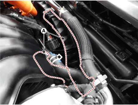
| 7. | Disconnect the HSG sensor connector (A).
|
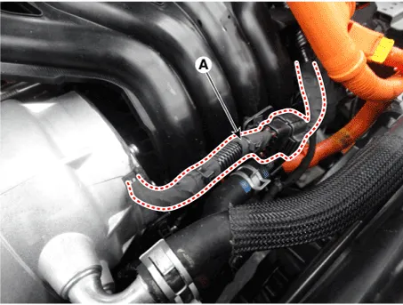
| 8. | Remove the cooler hose (A) from the HSG.
|
| 9. | Remove the intake manifold. (Refer to Engine Mechanical System - "Intake Manifold".) |
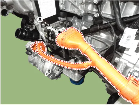
| 10. | Disconnect the HSG high-voltage cable connector (A).
|
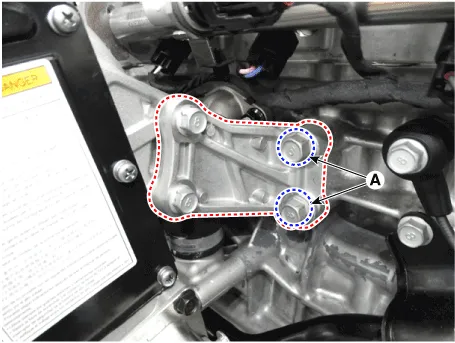
| 11. | Remove the HSG support bracket mountine bolts (A).
|
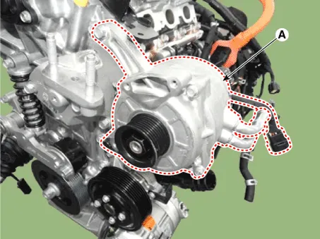
| 12. | Remove the HSG (A).
|
| Installation |
|
| 1. | To install, reverse the removal procedure. |
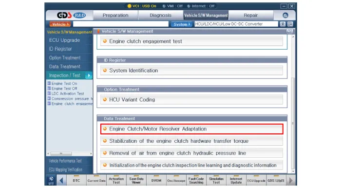
| 2. | Perform resolver sensor compensation. Perform compensation according to the GDS motor / HSG resolver compensation procedure shown below.
|
| 3. | Fill the coolant in the hybrid cooling system and use the GDS to perform air bleeding. (Refer to Hybrid Motor Cooling System - "Coolant".) |
| 4. | Check for the leakage in the hose connections while the engine is running. |
| Inspection |
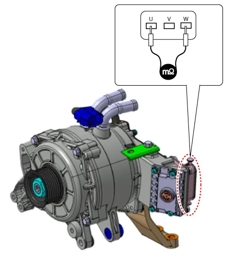
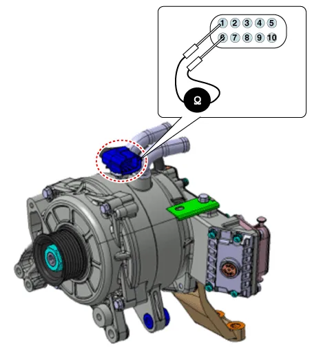
| 1. | Use the mΩ tester to check the line resistance.
|
| 2. | Check the temperature sensor resistance.
|
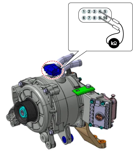
| 3. | Check the resolver sensor resistance.
|
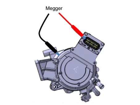
| 4. | Perform the insulation test.
|
Specifications Classification Unit Specifications VoltageVdc204DrivingTorqueNm / rpm / sec35.
Other information:
Hyundai Ioniq (AE) 2017-2022 Service & Repair Manual: Front Radar Unit. Repair procedures
Removal1.Remove the front bumper.(Refer to Body - "Front Bumper")2.Disconnect the smart cruise control unit connector (A).3.Remove the smart cruise control nuit assembly (B) from thevehicle after loosening mounting bolts.Installation1.Install in the reverse order of removal.
Hyundai Ioniq (AE) 2017-2022 Service & Repair Manual: Description and operation
System OverviewParking Distance Warning (PDW) is an electronic driving aid that warns the driver to be cautious while parking or driving at low speed. The sensor uses ultrasonic waves to detect objects within proximity of the vehicle.PDW consists of four RPS sensors which are detecting the obstacles and transmit the result separated into three war
Categories
- Manuals Home
- Hyundai Ioniq Owners Manual
- Hyundai Ioniq Service Manual
- Transmission Gear Oil. Repair procedures
- Theft-alarm System
- Engine Clutch System
- New on site
- Most important about car
