Hyundai Ioniq (AE): Parking Brake System / Parking Brake Switch. Repair procedures
| Removal |
| 1. | Disconnect the negative (-) battery cable. |
| 2. | Remove the crash pad lower panel. (Refer toBody - "Crash Pad") |
| 3. | Remove the junction box. (Refer to Body Electrical System - "Fuses and Relays") |
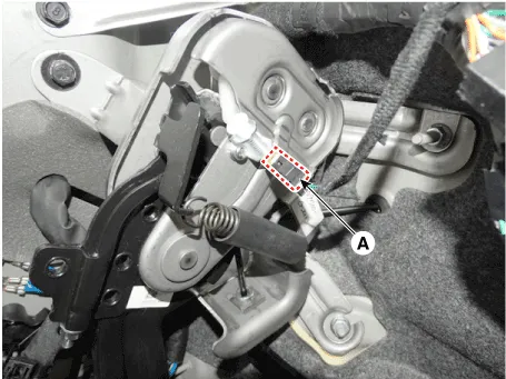
| 4. | Disconnect the parking brake switch connector (A).
|
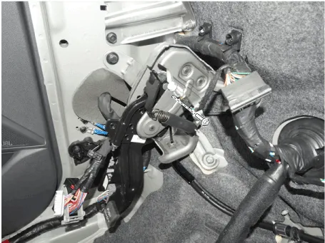
| 5. | Loosen the screw and then remove the parking brake switch.
|
| 6. | Install in the reverse of removal. |
RemovalParking Brake Pedal1.Disconnect the negative (-) battery cable.2.Remove the crash pad lower panel.(Refer to Body - "Crash Pad")3.Remove the junction box.
Removal1.Disconnect the negative (-) battery cable.2.Release the parking brake.3.Remove the crash pad lower panel.(Refer to Body - "Crash Pad")4.Remove the parking brake cable adjusting nut (A) and the fixing clip (B), and then remove the parking cable from the brake pedal.
Other information:
Hyundai Ioniq (AE) 2017-2022 Service & Repair Manual: Description and operation
DescriptionThe smart cruise control system allows a driver to program the vehicle to control the speed and following distance by detecting the vehicle ahead without depressing the brake pedal and the accelerator pedal.1.Cruise speed control : The vehicle maintains the selected speed if there are not vehicles ahead.
Hyundai Ioniq (AE) 2017-2022 Service & Repair Manual: Specifications
S
Categories
- Manuals Home
- Hyundai Ioniq Owners Manual
- Hyundai Ioniq Service Manual
- Transmission Gear Oil. Repair procedures
- Suspension System
- Engine Control/Fuel System
- New on site
- Most important about car
