Hyundai Ioniq (AE): Power Door Mirrors / Power Door Mirror Assembly. Repair procedures
Hyundai Ioniq (AE) 2017-2022 Service & Repair Manual / Body Electrical System / Power Door Mirrors / Power Door Mirror Assembly. Repair procedures
| Inspection |
| 1. | Disconnect the negative (-) battery terminal. |
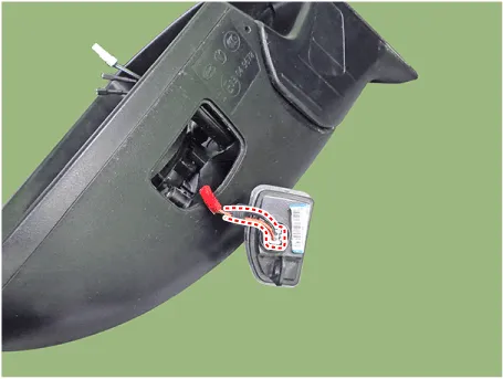
| 2. | Remove the front door quadrant inner cover (A).
|
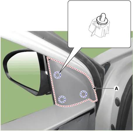
| 3. | Disconnect the power door mirror connector from the harness.
|

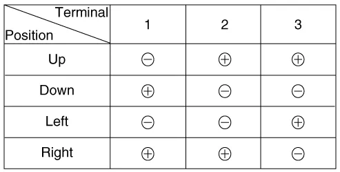
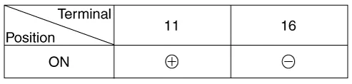
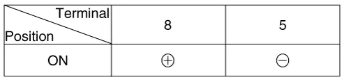
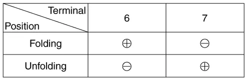
| 4. | Apply battery voltage to each terminal as shown in the table and verify that the mirror operates properly. [Mirror Control (LH/RT)]
[BSD Indicator]
[Mirror Heater]
[Side Repeater Lamp]
[Mirror Fording Motor]
|

| Removal |
| 1. | Disconnect (-) battery terminal. |
| 2. | Remove door mirror assembly. (Refer to Body - "Outside View Mirror") |
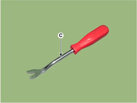
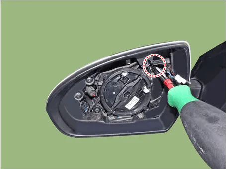
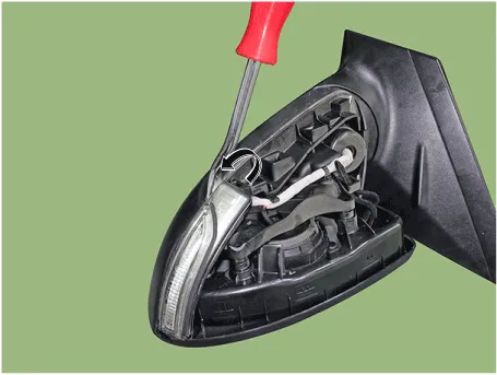
| 3. | Using a fastener remover (C), remove the mirror (A) as illustration below.
|
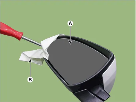

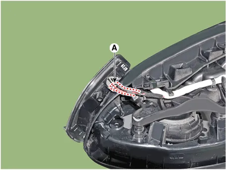
| 4. | Disconnect heat wire connectors (A),(B) and then remove the mirror.
|
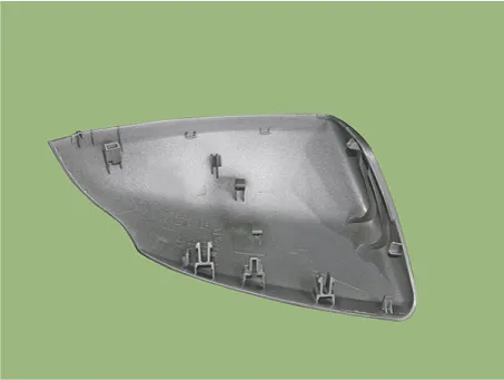
| 5. | Remove the scalp.
|

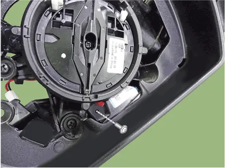
| 6. | Remove front cover and LED side repeater lamp lock screw.
|
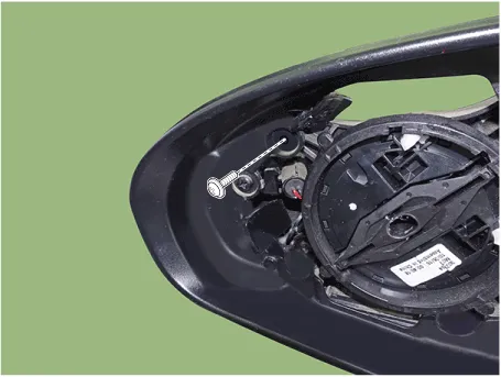
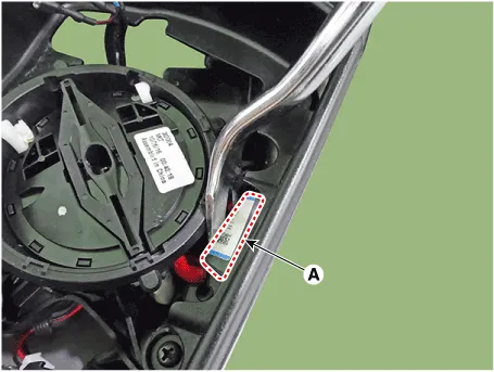
| 7. | Using a fastener remover, remove the LED side repeater lamp as illustration below.
|
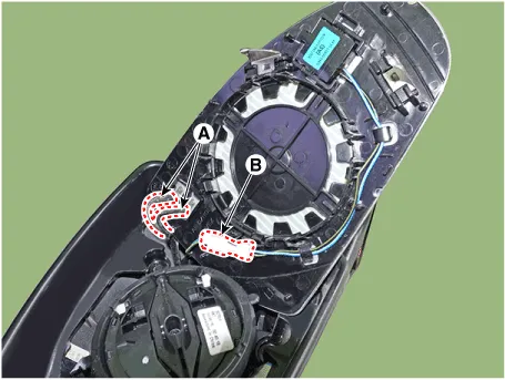
| 8. | Disconnect the connector (A) and then remove the LED side repeater lamp (A).
|
| 9. | Loosen the puddle lamp mounting screw.
|
| 10. | Using a fastener remover, remove the puddle lamp (A) as illustration below.
|
| 11. | Disconnec the connector and then remove the puddle lamp.
|
| Installation |
| 1. | Install the puddle lamp. |
| 2. | Install the LED side repeater lamp. |
| 3. | Install the scalp.
|
| 4. | Connect mirror heat wire connector and BSD connector then mount mirror. |
| 5. | Install the door mirror assembly. |
| 6. | Connect (-) battery terminal then check if door mirror lamp works normally. |
Components1. BSD Indicator2. Side repeater lamp3. Puddle lamp
Other information:
Hyundai Ioniq (AE) 2017-2022 Service & Repair Manual: Specifications
S
Hyundai Ioniq (AE) 2017-2022 Service & Repair Manual: Description and operation
System OverviewParking Distance Warning (PDW) is an electronic driving aid that warns the driver to be cautious while parking or driving at low speed. The sensor uses ultrasonic waves to detect objects within proximity of the vehicle.PDW consists of four RPS sensors which are detecting the obstacles and transmit the result separated into three war
Categories
- Manuals Home
- Hyundai Ioniq Owners Manual
- Hyundai Ioniq Service Manual
- Brake System
- Repair procedures
- How to Connect Portable Charger (ICCB: In-Cable Control Box)
- New on site
- Most important about car

Copyright © 2026 www.hioniqae.com - 0.0134