Hyundai Ioniq (AE): Rear Suspension System / Rear Stabilizer Bar. Repair procedures
| Removal |
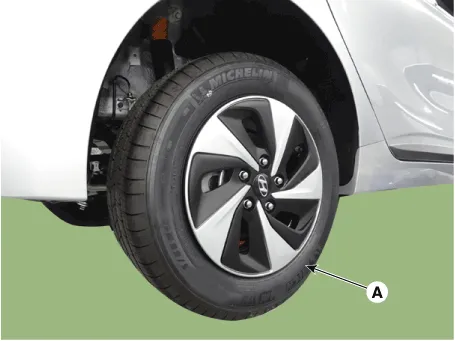
| 1. | Loosen the wheel nuts slightly. Raise the vehicle, and make sure it is securely supported. |
| 2. | Remove the rear wheel and tire (A) from the rear hub.
|

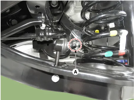
| 3. | Loosen the nut and then remove the rear stabilizer link (A).
|
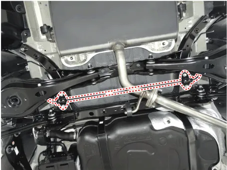
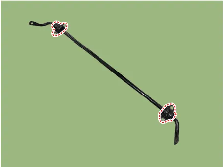
| 4. | Loosen the mounting bolt and then remove the stabilizer bar from the rear cross member.
|
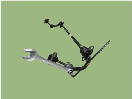
| 5. | Remove the stabilizer link from the rear lower arm.
|
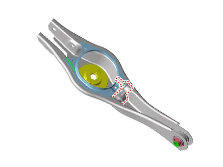
| 6. | Remove the bushing.
|
| 7. | Install in the reverse order of removal. |
| Inspection |
| 1. | Check the rear stabilizer bar for deformation. |
| 2. | Check the rear stabilizer link ball joint for damage. |
Removal1.Loosen the wheel nuts slightly.Raise the vehicle, and make sure it is securely supported.2.Remove the rear wheel and tire (A) from the rear hub.
Removal1.Loosen the wheel nuts slightly.Raise the vehicle, and make sure it is securely supported.2.Remove the rear wheel and tire (A) from the rear hub.
Other information:
Hyundai Ioniq (AE) 2017-2022 Service & Repair Manual: Evaporator Temperature Sensor. Description and operation
DescriptionThe evaporator temperature sensor will detect the evaporator core temperature and interrupt compressor relay power in order to prevent evaporator from freezing by excessive cooling. The evaporator temperature sensor has the Negative Temperature Coefficient (NTC).
Hyundai Ioniq (AE) 2017-2022 Service & Repair Manual: Smart Cruise Control (SCC) Switch. Repair procedures
Removal1.Disconnect the negative (-) battery terminal.2.Remove the steering wheel assembly.(Refer to Steering System -"Steering Wheel")3.Remove the steering back cover (A).4.Remove the steering remote control connector (A).5.Remove the steering remote control (A), after loosening the screws.
Categories
- Manuals Home
- Hyundai Ioniq Owners Manual
- Hyundai Ioniq Service Manual
- Brake System
- Checking the Coolant Level
- If the 12 Volt Battery is Discharged (Hybrid Vehicle)
- New on site
- Most important about car
