Hyundai Ioniq (AE): AHB(Active Hydraulic Boost) System / Repair procedures
| AHB Brake System Bleeding Procedure |
|

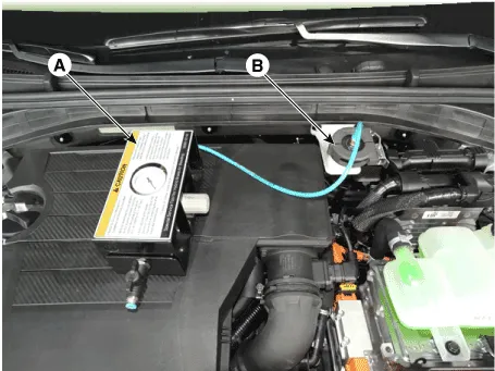
| 1. | Before installing the SST on the vehicle, close the airshut-off valve (A) to adjust the pressure gauge to thestandard value.
|
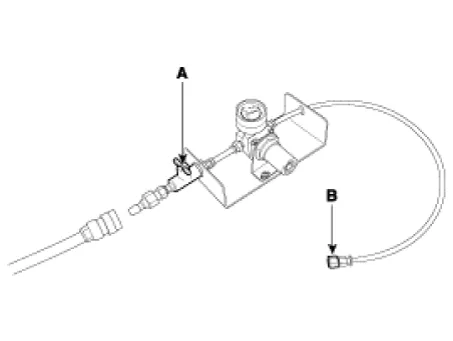
| 2. | After connecting an air hose and opening the airshut-off valve (A), adjust the pressure gauge (B) withto the standard value.
|
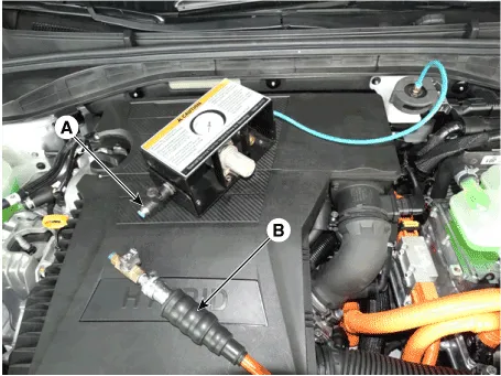
| 3. | close the air shut off valve (A) and remove the plug (B).
|
| 4. | Remove the brake reservoir tank cap. |
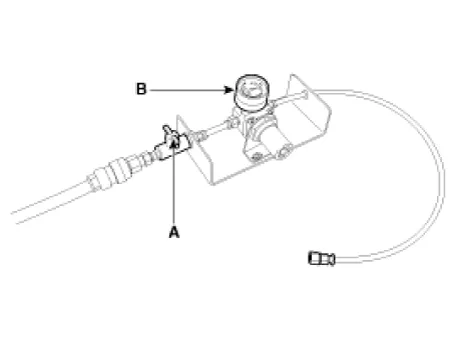
| 5. | Install the cap (A) of SST (0K585-E8100) on thereservoir tank.
|
| 6. | Make sure the check valve (A) is closed and connect SST (09580-3D100) (A) to the adapter (B).
|
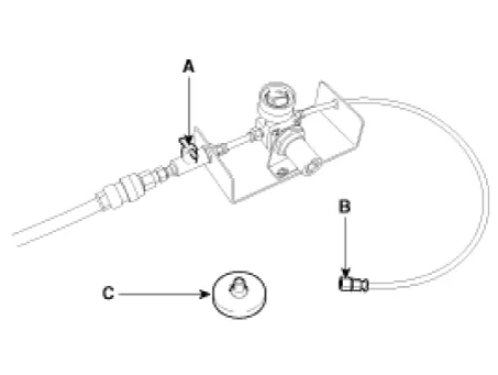
| 1. | To remove the SST (09580-3D100) from the vehicle,close the air shut-off valve (A) first.
|
| 2. | Remove SST (09580-3D100) and the cap of SST (0K585-E8100) on the reservoir tank.
|

| 3. | Inatall the brake reservoir tank cap. |
| Bleeding Step 1 (IBAU ECU OFF) |
|
| 1. | Disconnect the negative (-) battery terminal to turn off IBAU ECU. |
| 2. | Set the air bleeding tool (SST : 09580-3D100) and the cap of SST (0K585-E8100) to reservoir tank and make pressure (0.3 - 0.35 MPa (43.5 - 50.7 psi)) to it.
|

| 3. | Initiate air bleeding on all bleed screws in the following sequences until air bubbles no longer appear in the fluid. After air bleeding, close the bleed screws. ①IBAU (2 bleed srews) ② 4 wheels (RR -> RL -> FR -> FL)
|
| 4. | Perform air bleeding while stepping on the brake pedal and opening bleed screws; then, close bleed screws and release the brake pedal. Perform this procedure 10 times.
|
| Bleeding Step 2 (IBAU ECU ON) |
| 1. | Connect the negative (-) battery terminal to turn on IBAU ECU. |
| 2. | Start the engine. |
| 3. | Set the front wheels straight forward and the shift lever knob in Parking. |
| 4. | If the ESC function is completely turned off after about 3 seconds with the ESC Off switch held down, hold the ESC OFF switch and operate the brake pedal 10 times in full stroke. And then turn off the engine.
|
| 5. | Start the engine. And then press the ESC OFF switch for more than 3 seconds to enter ESC OFF mode.
|

| 6. | Use the air bleeding tool (SST : 09580-3D100, 0K585-E8100) and feed oil pressure 0.3 - 0.35 MPa (43.5 - 50.7 psi) into the reservoir. Loosen the bleed screws on 4 wheels; then, initiate air bleeding and close them while depressing the brake pedal half stroke continuously. Perform it 10 times; then, release the brake pedal. Bleed screw sequence : ③ 4 wheels
|
| 7. | Connect the GDS to the data link connector located underneath the dash panel and perform "Fluid Circulation Mode" on GDS. |
Terminal FunctionIBAU Connector Input / Output No Description No Description 1E/R Fuse & Relay Box(Multi Fuse - AHB)24Electric Parking Brake Switch(Auto Hold Swutch)2PSU Motor (+)25-3-26Parking Brake Switch4Shield Cable Ground27Rear Wheel Sensor LH (SIG)5E/R Fuse & Relay BoxPSU Motor (GND)28Front Wheel Sensor LH (SIG)6Brake Pedal Module (PDT PWR) 29Driver Door Switch7Brake Pedal Module (PDF PWR)30E/R Fuse & Relay Box(Multi Fuse - AHB 2)8E/R Fuse & Relay Box(Stop Signal Electronic Module)31Brake Pedal Module (PDF GND)9-32-10Brake Pedal Module (PDT GND)33Rear Wheel Sensor LH (VCC)11Shield Cable Ground34Rear Wheel Sensor RH (VCC)12-35-13PSU Motor (-)36Brake light switch14Ground 37-15-38C-CAN (High)16Crash Pad Switch (ESC OFF Switch)39C-CAN (Low)17Front Wheel Sensor LH (VCC)40Vehicle Speed :Smart Key Control Module, PCM18Front Wheel Sensor RH (VCC)41-19P-CAN (High)42Front Wheel Sensor RH (SIG)20P-CAN (Low)43Rear Wheel Sensor RH (SIG)21ESS Drive44Stop Lamp Switch22Brake Pedal Module (PDT SIG)45- 23Brake Pedal Module (PDF SIG)46Ground (GE06)
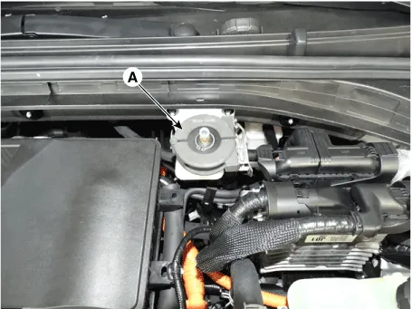
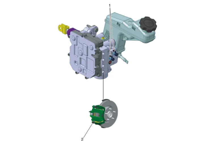
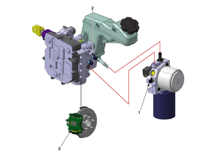
Components • IBAU (Intergrated Brake Actuation Unit) must not be disassembled.1. Intergrated Brake Actuation Unit (IBAU) ECU2.
Other information:
Hyundai Ioniq (AE) 2017-2022 Service & Repair Manual: Heater Unit. Components and components location
Component Location1. Heater unit assemblyCompoents1. Heater core cover2. Heater core & Seal assembly3. Mode actuator [LH]4. Temperature control actuator [LH]5. Shower duct [LH]6. Duct sensor [Floor]7. PTC Heater8. Duct sensor [Vent]9. Heater & Evaporator lower case10.
Hyundai Ioniq (AE) 2017-2022 Service & Repair Manual: Repair procedures
Removal1.Disconnect the negative (-) battery terminal.2.Remove the tailgate lid trim.(Refer to Body - "TailGate Lid Trim")3.Disconnect the Rear view camera connector (A).4.Remove the Rear view camera assembly after loosening the mounting screws.Installation1.
Categories
- Manuals Home
- Hyundai Ioniq Owners Manual
- Hyundai Ioniq Service Manual
- Hybrid Vehicle Engine Compartment
- Engine Control/Fuel System
- Body (Interior and Exterior)
- New on site
- Most important about car
