Hyundai Ioniq (AE): Gear Actuator Assembly / Repair procedures
| Removal |
|

|

|

| 1. | Shut off the High Voltage circuit. (Refer to General Information - "High Voltage Shutoff Procedure") |
| 2. | Remove the engine room under cover. (Refer to Engine And Transaxle Assembly - "Engine Room Under Cover") |
| 3. | Loosen the drain plug, and drain the inverter coolant. Remove the reservoir cap to help drain the coolant faster. (Refer to Hybrid Motor System - "Coolant") |
| 4. | Remove the HPCU (Hybrid Power Control Unit). (Refer to Hybrid Control System - "Hybrid Power Control Unit (HPCU)") |
| 5. | Remove the ECM (Engine Control Module) and TCM (Transmssion Control Module). (Refer to Engine Control/Fuel System - "Engine Control Module (ECM)") (Refer to Dual Clutch Control System - "DCT Control Module (TCM)") |
| 6. | Remove the HPCU (Hybrid Power Control Unit) tray. (Refer to Hybrid Control System - "Hybrid Power Control Unit (HPCU)") |
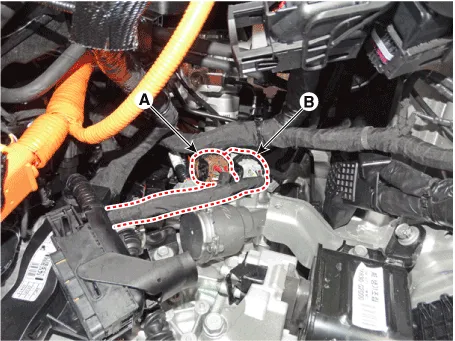
| 7. | Disconnect the gear actuator motor connector (A) and solenoid connector (B).
|
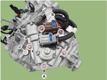
| 8. | Remove the gear actuator assembly after loosening bolts (A-3ea, B-2ea).
|
| Installation |
| 1. | Install in the reverse order of removal.
|
Circuit Diagram
Other information:
Hyundai Ioniq (AE) 2017-2022 Service & Repair Manual: emperature Control Actuator. Description and operation
DescriptionThe temperature control actuator is located at the heater unit. It regulates the temperature by the procedure as follows. The signal from the control unit adjusts the position of the temperature door by operating the temperature switch. Then the temperature will be regulated by the hot/cold air ratio decided by the position of the temper
Hyundai Ioniq (AE) 2017-2022 Service & Repair Manual: General safety information and caution
General Safety Information and CautionBe careful of the following precautions when driving the vehicle using the smart cruise control system. • The smart cruise control system may have limits in detecting distance to the vehicle ahead due to road and traffic conditions.
Categories
- Manuals Home
- Hyundai Ioniq Owners Manual
- Hyundai Ioniq Service Manual
- Hybrid Control System
- Repair procedures
- Engine Control/Fuel System
- New on site
- Most important about car

Copyright © 2026 www.hioniqae.com - 0.0136