Hyundai Ioniq (AE): SRSCM / Schematic diagrams
| Circuit Diagram |
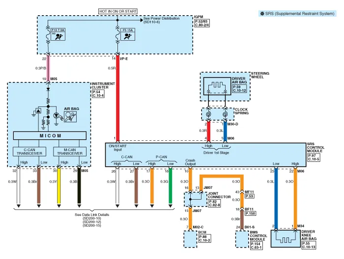
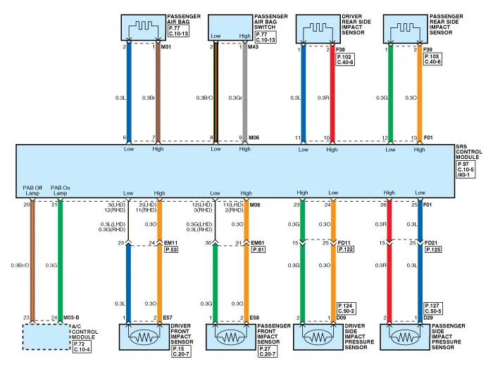

Components1. Supplemental Restraint System Control Module (SRSCM)2. Pressure Side Impact Sensor (P-SIS)3. Front right Pressure Impact Sensor (FIS)4. Front left Pressure Impact Sensor (FIS)5.
Description• Supplemental Restraint System Control Module (SRSCM) determines whether and when to deploy air bag module, seat belt pretensioner (BPT) and emergency fastenig device (EFD).
Other information:
Hyundai Ioniq (AE) 2017-2022 Service & Repair Manual: Intake Actuator. Repair procedures
Inspection1.Turn the ignition switch OFF.2.Disconnect the intake actuator connector.3.Verify that the intake actuator operates to the fresh position when connecting 12V to terminal 3 and grounding terminal 4.Verify that the intake actuator operates to the recirculation position when connected in reverse.
Hyundai Ioniq (AE) 2017-2022 Service & Repair Manual: General safety information and caution
General Safety Information and CautionBe careful of the following precautions when driving the vehicle using the smart cruise control system. • The smart cruise control system may have limits in detecting distance to the vehicle ahead due to road and traffic conditions.
Categories
- Manuals Home
- Hyundai Ioniq Owners Manual
- Hyundai Ioniq Service Manual
- Repair procedures
- Troubleshooting
- DCT(Dual Clutch Transmission) System
- New on site
- Most important about car
