
Hyundai Ioniq (AE): Seat Electrical / Seat Heater. Components and components location
Hyundai Ioniq (AE) 2017-2022 Service & Repair Manual / Body Electrical System / Seat Electrical / Seat Heater. Components and components location
| Component Location |
[Front Seat Heater (Non-Air ventilation)]
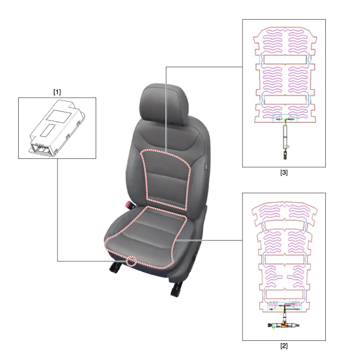
| 1. Seat heater unit (Passenger seat only) 2. Seat chusion heater | 3. Seat back (Heater) |
[Front Seat Heater (Air ventilation)]
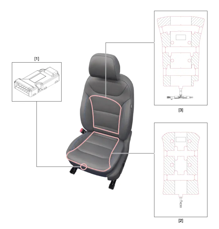
| 1. Air ventilation unit (Passenger seat only) 2. Seat cushion (Heater) | 3. Seat back (Heater) |
[Rear Seat Heater]
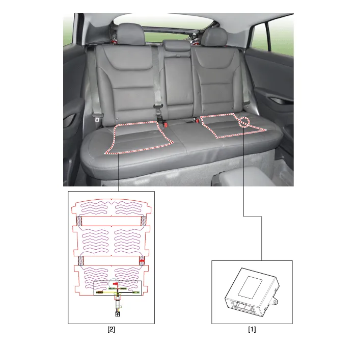
| 1. Rear seat heater unit (Passenger seat only) | 2. Seat cushion (Heater) |
InspectionSeat Control Switch1.With the power seat switch in each position, make sure that continuity exists between the terminals below. If continuity is not as specified, replace the power seat switch.
Circuit Diagram[Front Seat Heater (Non-Air Ventilation)][Rear Seat Heater (Bench Type)]
Other information:
Hyundai Ioniq (AE) 2017-2022 Service & Repair Manual: Photo Sensor. Repair procedures
Inspection1.Turn the ignition switch ON.2.Connect the GDS.3.Emit intensive light toward the photo sensor using a lamp, and check the output voltage change.4.The voltage will rise with higher intensive light and reduce with lower intensive light.1. Auto light signal2.
Hyundai Ioniq (AE) 2017-2022 Service & Repair Manual: Components and components location
C
Categories
- Manuals Home
- Hyundai Ioniq Owners Manual
- Hyundai Ioniq Service Manual
- Suspension System
- Jump starting procedure
- Front Disc Brake. Repair procedures
- New on site
- Most important about car

Copyright В© 2026 www.hioniqae.com - 0.011