Hyundai Ioniq (AE): DCT(Dual Clutch Transmission) System / Special service tools
| Special Service Tools |
|
Tool (Number and Name)
|
Illustration
|
Use
|
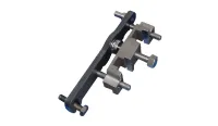
| 09200-3N000 Engine support fixture (Beam) |
| Removal and installation of the transaxle. Use this beam (SST No. : 09200-3N000) with the supporter (SST No. : 09200-2S000). ※Permit operating with 09200-38001. ※Refer to the engine support fixture assembly drawing below. |
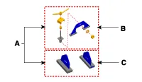
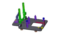
| A : 09200-2S000 B : 09200-2S100 C : 09200-2S200 Engine support fixture (Supporter) |
| Removal and installation of the transaxle. Use this beam (SST No. : 09200-38001/3N000) with the supporter (SST No. : 09200-2S000). ※Refer to the engine support fixture assembly drawing below. |
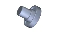
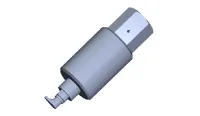
| 09430-C1190 Oil seal installer |
| Used for installing differential oil seal of both side Used with the handle (09231-H1100) |
| 09231-H1100 Handle |
| Used with the oil seal installer when installing oil seal |
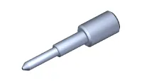
| 09480-A3800 Inhibitor switch neutral fixed pin |
| When installing the manual control lever on the inhibitor switch, used to align the neutral position. |
| 09430-C1180 Dual clutch remover |
| Used for removing dual clutch assembly |
| 09430-2A240 Dual clutch Installer |
| Used for installing dual clutch assembly |
| 09430-G2100 Clutch actuator remover |
| Used for removing clutch actuator assembly |
| 09430-F0100 Actuator fixing jig & Motor shaft reset tool |
| Used for adjusting clutch actuator Used with the Clutch actuator adjuster (09430-C1300) |
| 09430-C1300 Clutch abrasion compensation tool |
| Used for adjusting clutch actuator Used with the Clutch actuator adjustment jig (09430-F0100) |
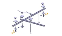


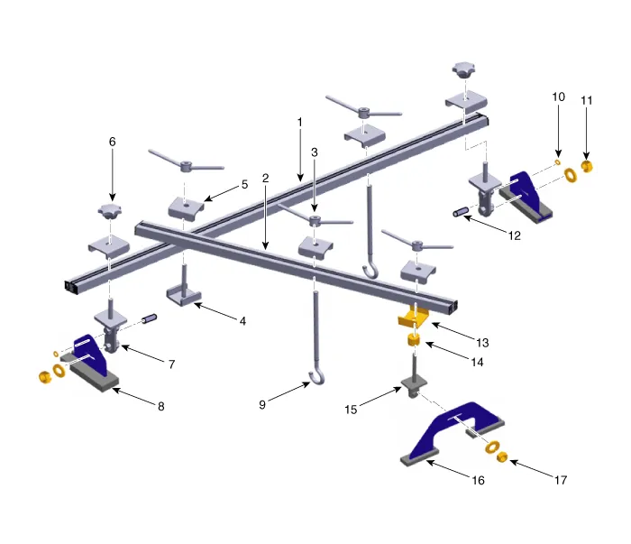
| 1. 09200-3N000(Main bar) 2. 09200-3N000(Sub bar) 3. 09200-3N000(Handle) 4. 09200-3N000(Stopper) 5. 09200-3N000(Stopper) 6. 09200-3N000(Knobe) 7. 09200-3N000(Adaptor) 8. 09200-2S000(Supporter) 9. 09200-3N000(Hanger) | 10. 09200-3N000(Clip) 11. 09200-3N000(Nut) 12. 09200-3N000(Pin) 13. 09200-2S000(Stopper) 14. 09200-2S000(Spacer) 15. 09200-2S000(Adaptor) 16. 09200-2S000(Supporter) 17. 09200-2S000(Nut) |
Specifications Transmission type D6KF1 Engine TypeKappa 1.6 GDITransmssion fluidQuantity1.6 - 1.7 L(0.
Troubleshooting Trouble symptom Probable cause Remedy Displayed the warning lamp "E"(Driving is only possible with 1/ R gear)Not performed DCT learningPerform the DCT manual learning procedure.
Other information:
Hyundai Ioniq (AE) 2017-2022 Service & Repair Manual: Climate Control Air Filter. Repair procedures
Replacement1.Disconnect the air damper (A) from the glove box (B).2.Remove the stopper (B) from the glove box (A).3.Remove the filter cover (A) by pressing the knob.4.Replace the air filter (A) with a new one according to the direction of air filter. • To remove the filter easily, press the right side inwa
Hyundai Ioniq (AE) 2017-2022 Service & Repair Manual: Cruise Control Switch. Repair procedures
Removal1.Disconnect the negative (-) battery terminal.2.Remove the steering wheel assembly.(Refer to Steering System - "Steering Wheel")3.Remove the steering back cover (A).4.Remove the steering remote control connector (A).5.Remove the steering remote control after loosening the screws.
Categories
- Manuals Home
- Hyundai Ioniq Owners Manual
- Hyundai Ioniq Service Manual
- How to Connect Portable Charger (ICCB: In-Cable Control Box)
- DCT(Dual Clutch Transmission) System
- Engine Mechanical System
- New on site
- Most important about car
