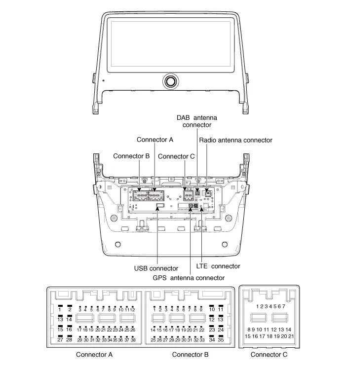
Hyundai Ioniq (AE): AVN System / AVN(Audio Video Navigation) head unit. Components and components location
| Components |

|
No
|
Connector A
|
Connector B
|
Connector C
|
| 1 | - | - | B CAN (High) |
| 2 | - | Mic signal (+) | P CAN (High) |
| 3 | AMP NAVI VOICE (+) | - | IGN3 Wake up |
| 4 | AM SPDIF (High) | - | - |
| 5 | - | Antenna power | - |
| 6 | Camera power | Illumination (+) | - |
| 7 | Camera Video | MM Can (High) | - |
| 8 | - | - | B CAN (Low) |
| 9 | - | - | P CAN (Low) |
| 10 | - | Battery (+) | - |
| 11 | DTC | Battery (+) | - |
| 12 | Steering wheel remote control | Ground | - |
| 13 | - | Ground | - |
| 14 | - | - | - |
| 15 | - | Mic signal (-) | - |
| 16 | - | - | - |
| 17 | AMP NAVI VOICE (-) | - | - |
| 18 | AMP SPDIF (Low) | - | - |
| 19 | AMP SPDIF Ground | Illumination (-) | - |
| 20 | Camera power ground | MM Can (Low) | - |
| 21 | Camera video ground | - | - |
| 22 | - | ACC | |
| 23 | - | - | |
| 24 | - | - | |
| 25 | - | - | |
| 26 | Steering wheel remote constrol ground | - | |
| 27 | - | - | |
| 28 | - | - | |
| 29 | - | - | |
| 30 | - | - | |
| 31 | - | - | |
| 32 | - | - | |
| 33 | Camera shield ground | IGN 1 | |
| 34 | - | - | |
| 35 | - | - | |
| 36 | - | ||
| 37 | - | ||
| 38 | Speed |
DescriptionAVN SystemThe AVN system has improved information search and easiness of manipulation for the driver by simplifying the system operation experience and unifying the display of the user information such as multimedia and car information.
Removal1.Disconnect the negative (-) battery terminal.2.Remove the cluster fascia panal.(Refer to Body - "Center Fascia Panal")3.Remove the crash pad garnish RH.
Other information:
Hyundai Ioniq (AE) 2017-2022 Service & Repair Manual: Rear Corner Radar Unit. Repair procedures
Removal1.Disconnect the negative (-) battery terminal.2.Remove the rear bumper.(Refer to Body - "Rear Bumper")3.Remove the rear corner radar unit (A) after loosening the mounting nuts. • Take care not to separate the bracket from rear bumper when removing the rear corner radar sensor.
Hyundai Ioniq (AE) 2017-2022 Service & Repair Manual: Cruise Control Switch. Repair procedures
Removal1.Disconnect the negative (-) battery terminal.2.Remove the steering wheel assembly.(Refer to Steering System - "Steering Wheel")3.Remove the steering back cover (A).4.Remove the steering remote control connector (A).5.Remove the steering remote control after loosening the screws.
Categories
- Manuals Home
- Hyundai Ioniq Owners Manual
- Hyundai Ioniq Service Manual
- If the 12 Volt Battery is Discharged (Hybrid Vehicle)
- Transmission Gear Oil. Repair procedures
- Suspension System
- New on site
- Most important about car
