Hyundai Ioniq (AE): AVN System / AVN Remote Controller. Schematic diagrams
Hyundai Ioniq (AE) 2017-2022 Service & Repair Manual / Body Electrical System / AVN System / AVN Remote Controller. Schematic diagrams
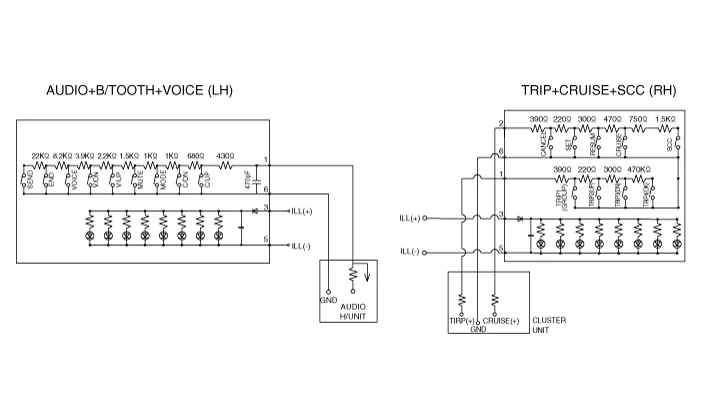
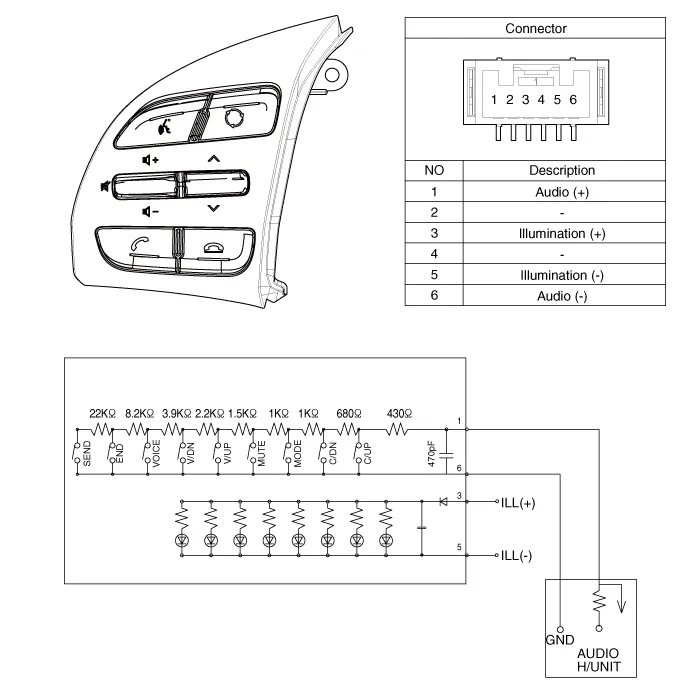
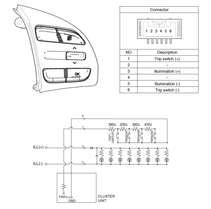
| Circuit Diagram |
[Audio+B/Tooth]

[Audio+B/Tooth+Voice]
[Trip]
[Trip+Cruise]
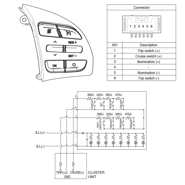
[Trip+Cruise+SCC]

Components1. Left Remote Control Switch (Audio + Hands free)2. Right Remote Control Switch(Cruise+Trip Computer)
Inspection1.Check for resistance between terminals in each switch position (LH).[LH : Audio+B/TOOTH+VOICE] Switch Connector terminal Resistance (±5%) SEEK Up1-6430 ΩSEEK Down1.
Other information:
Hyundai Ioniq (AE) 2017-2022 Service & Repair Manual: Mode Control Actuator. Repair procedures
Inspection1.Turn the ignition switch OFF.2.Disconnect the mode control actuator connector.3.Verify that the mode control actuator operates to the defrost mode when connecting 12V to terminal 3 and grounding terminal 4.Verify that the mode control actuator operates to the vent mode when connected in reverse.
Hyundai Ioniq (AE) 2017-2022 Service & Repair Manual: Components and components location
C
Categories
- Manuals Home
- Hyundai Ioniq Owners Manual
- Hyundai Ioniq Service Manual
- If the 12 Volt Battery is Discharged (Hybrid Vehicle)
- DCT(Dual Clutch Transmission) System
- Suspension System
- New on site
- Most important about car

Copyright © 2026 www.hioniqae.com - 0.0155