
Hyundai Ioniq (AE): High Voltage Battery Control System / Battery Current Sensor. Schematic diagrams
Hyundai Ioniq (AE) 2017-2022 Service & Repair Manual / Hybrid Control System / High Voltage Battery Control System / Battery Current Sensor. Schematic diagrams
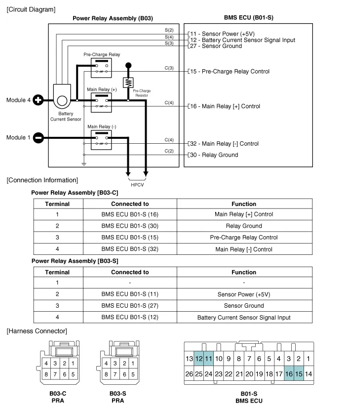
| Circuit Diagram |
Specification Current (A) Output Voltage (V) -300 (Charge)0.502.5+300 (Discharge)4.5
Removal • Be sure to read and follow the "General Safety Information and Caution" before doing any work related with the high voltage system.
Categories
- Manuals Home
- Hyundai Ioniq Owners Manual
- Hyundai Ioniq Service Manual
- Body (Interior and Exterior)
- Suspension System
- Engine Mechanical System
- New on site
- Most important about car

Copyright © 2026 www.hioniqae.com - 0.0183