Hyundai Ioniq (AE): High Voltage Battery System / Battery Pack Assembly. Repair procedures
| Removal |
|

| 1. | Shut off the high voltage. (Refer to Hybrid Control System - "High voltage Shut-off Procedures") |
| 2. | Remove the rear seat cushion. (Refer to Body - "Rear Seat Assembly") |
| 3. | Remove the rear door scuff trim. (Refer to Body - "Door Scuff Trim") |
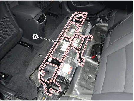
| 4. | Remove the upper frame (A) after loosening the mounting bolts and nuts.
|
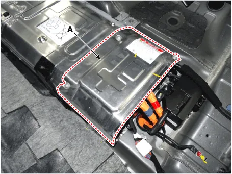
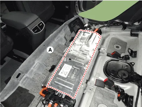
| 5. | Remove the high voltage battery rear cover (A) after loosening the mounting bolts and nuts.
|
| 6. | Remove the inlet cooling duct. (Refer to Hybrid Control System - "Cooling Duct") |
| 7. | Remove the high voltage power cable (+) terminal (A) and (-) terminal (B) after loosening the mounting bolts.
|

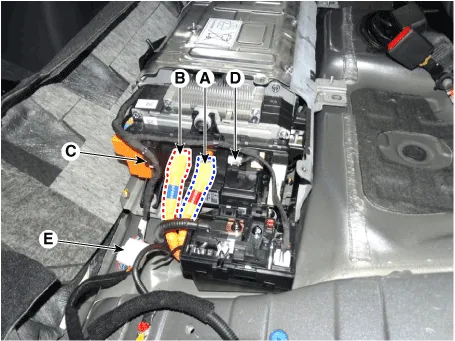
| 8. | Disconnect the inverter power connector [+] (A), inverter power connector [-] (B) and battery current sensor connector (C). |
| 9. | Disconnect the PRA connector (D).
|
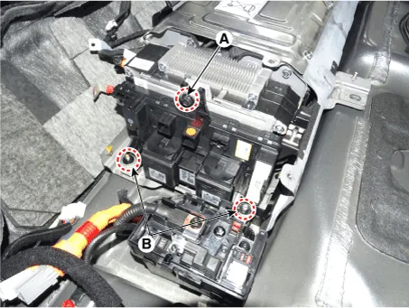
| 10. | Remove the installation bolt (A) and nut (B), then remove the power relay assembly.
|
| 11. | Remove the installation bolts and nut, then remove the high voltage battery front cover (A).
|
| 12. | Disconnect the BMS connector (A). |
| 13. | Remove the installation nut (B), then remove the BMS.
|

| 14. | Remove the outlet cooling duct. (Refer to Hybrid Control System - "Cooling Duct") |
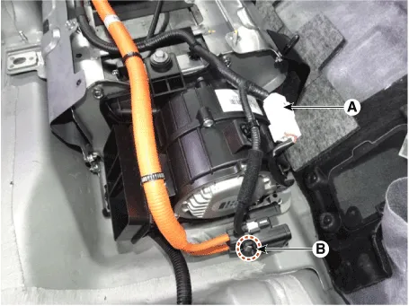
| 15. | Disconnect the cooling fan connector (A). |
| 16. | Remove the installation nut (B), then remove the safety plug cable.
|
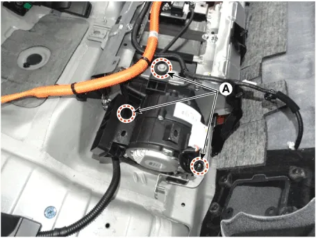
| 17. | Remove the installation bolts and nut (A), then remove the cooling fan.
|
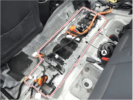
| 18. | Remove the installation bolts,then remove the high voltage battery pack (A).
|
| Installation |
|
| 1. | Install the high voltage battery pack in the reverse order of removal.
|
Inspection[Battery Pack Assembly Troubleshooting Chart] • For SOC check, refer to "SOC Inspection"• For voltage check, refer to "Battery Voltage Inspection"• For battery voltage sensing circuit, refer to "Voltage Sensing Circuit Inspection"• For isolation resistance check, refer to "Isolation Resistance Inspection" [SOC Level and Follow-up] SOC Symptom Warning Lamp Follow-up MIL Service Fuel • Normal --- 10 - 15% • Motor torque limite (Acceleration delay)--ON• Refuel and check the SOC againON--• Repair the MIL or Service Lamp related system• Charge the battery by starting the engine• Refuel if necessary ONON--ON-OnONON 5 - 10% • EV Mode inhibited • FATC Inhibited • LDC Inhibited --ON• Refuel and check the SOC againON--• Repair the MIL or Service Lamp related system• Charge the battery by starting the engine • Refuel if necessaryONON--ON-ONONON 0 - 5% • Impossible to start ON--• Repair the MIL or Service Lamp related system• Start the engine with GDS to charge the battery• Refuel if necessary ONON--ON-ONONON 0% ON--• Repair the MIL or Service Lamp related system• If necessary, Replace Battery Pack• Refuel if necessary [SOC Inspection]1.
Check the target charging voltage when replacing with a new module Fault Code1.Turn OFF the ignition switch.2.Connect the diagnostic tool device to the self-diagnosis connector (DLC).
Other information:
Hyundai Ioniq (AE) 2017-2022 Service & Repair Manual: Blower Unit. Components and components location
Component Location1. Blower unit assembly Components1. Duct Seal2. Intake duct case3. Air intake door assembly4. Intake door5. Seal6. Intake duct case (A)7. Air filter cover (A)8. Intake actuator9. Air filter cover10. Air filter 11. Blower unit pad12.
Hyundai Ioniq (AE) 2017-2022 Service & Repair Manual: Warning Indicator. Components and components location
C
Categories
- Manuals Home
- Hyundai Ioniq Owners Manual
- Hyundai Ioniq Service Manual
- Heating, Ventilation and Air Conditioning
- If the 12 Volt Battery is Discharged (Hybrid Vehicle)
- Hybrid Control System
- New on site
- Most important about car
