
Hyundai Ioniq (AE): High Voltage Battery Control System / Battery Temperature Sensor. Schematic diagrams
Hyundai Ioniq (AE) 2017-2022 Service & Repair Manual / Hybrid Control System / High Voltage Battery Control System / Battery Temperature Sensor. Schematic diagrams
| Circuit Diagram |
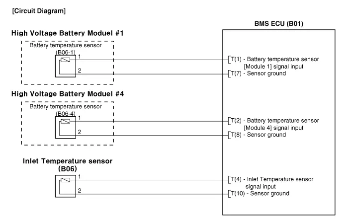
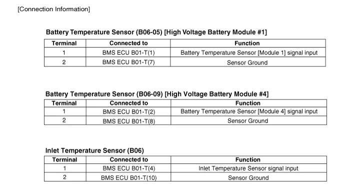

Specification[Air Inlet] Temperature Resistance (kΩ) °C °F -50-58314.
Removal • Be sure to read and follow the "General Safety Information and Caution" before doing any work related with the high voltage system.
Other information:
Hyundai Ioniq (AE) 2017-2022 Service & Repair Manual: Auto Defoging Actuator. Components and components location
C
Hyundai Ioniq (AE) 2017-2022 Service & Repair Manual: Parking Distance Warning (PDW) ON/OFF Switch. Repair procedures
Removal • Put on gloves to prevent hand injuries. • When removing with a flat-tip screwdriver or remover, wrap protective tape around the tools to prevent damage to components.
Categories
- Manuals Home
- Hyundai Ioniq Owners Manual
- Hyundai Ioniq Service Manual
- Troubleshooting
- Engine Control/Fuel System
- Jump starting procedure
- New on site
- Most important about car

Copyright © 2026 www.hioniqae.com - 0.0165