Hyundai Ioniq (AE): Rear View Monitor (RVM) / Components and components location
Hyundai Ioniq (AE) 2017-2022 Service & Repair Manual / Advanced Driver Assistance System (ADAS) / Rear View Monitor (RVM) / Components and components location
| Component Location |
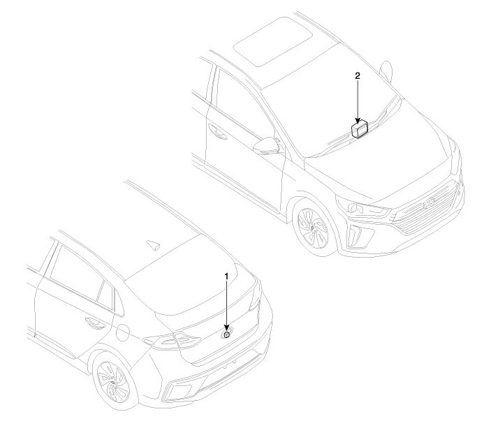
| 1. Rear view camera | 2. AVN monitor |
Circuit Diagram
Other information:
Hyundai Ioniq (AE) 2017-2022 Service & Repair Manual: Photo Sensor. Repair procedures
Inspection1.Turn the ignition switch ON.2.Connect the GDS.3.Emit intensive light toward the photo sensor using a lamp, and check the output voltage change.4.The voltage will rise with higher intensive light and reduce with lower intensive light.1. Auto light signal2.
Hyundai Ioniq (AE) 2017-2022 Service & Repair Manual: Intake Actuator. Components and components location
C
Categories
- Manuals Home
- Hyundai Ioniq Owners Manual
- Hyundai Ioniq Service Manual
- General Information
- Troubleshooting
- Checking the Coolant Level
- New on site
- Most important about car

Copyright © 2026 www.hioniqae.com - 0.0117