Hyundai Ioniq (AE): Immobilizer System / Description and operation
Hyundai Ioniq (AE) 2017-2022 Service & Repair Manual / Body Electrical System / Immobilizer System / Description and operation
| Description |
The immobilizer system will disable the vehicle unless the proper ignition key is used, in addition to the currently available anti-theft systems such as car alarms, the immobilizer system aims to drastically reduce the rate of auto theft.
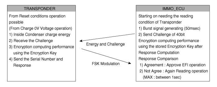
| 1. | Transponder (TP) – IMMO ECU Communication
TP Read Protocol
|
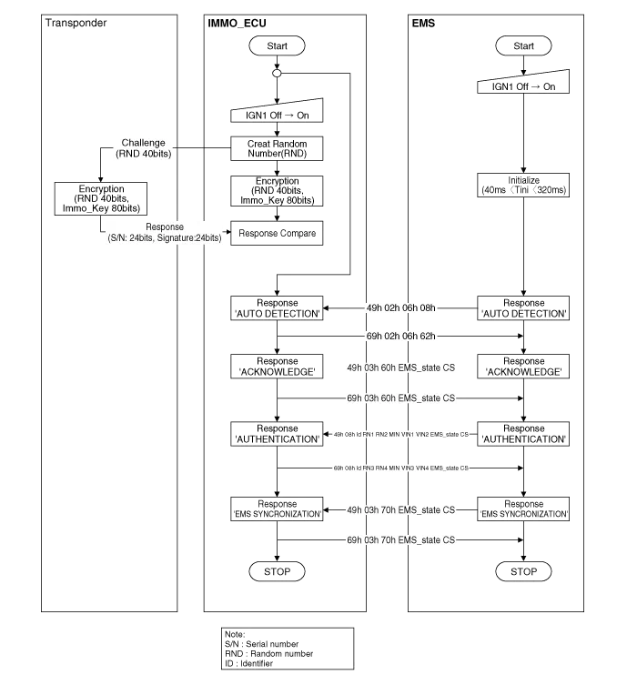
| 2. | Transponder / IMMO ECU / EMS authentication
|
| Components Operations |
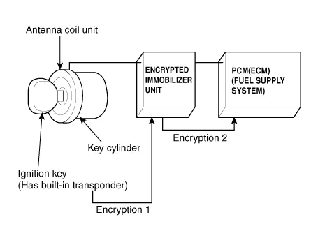
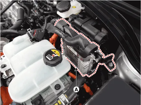
PCM (Power Train Control Module)
| 1. | The PCM (ECM) (A) carries out a check of the ignition key using a special encryption algorithm, which is programmed into the transponder as well as the PCM (ECM) simultaneously. Only if the results are equal, the engine can be started. The data of all transponders, which are valid for the vehicle, are stored in the PCM (ECM). ERN (Encrypted Randorm Number) value between EMS and encrypted smartra unit is checked and the validity of coded key is decided by EMS.
|
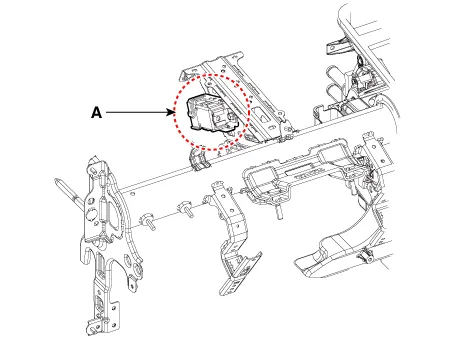
Encrypted Immobilizer Unit (A)
The IMMOBILIZER carries out communication with the built-in transponder in the ignition key. This wireless communication runs on RF (Radio frequency of 125 kHz). The IMMOBILIZER is mounted behind of the crash pad close to center cross bar.
The RF signal from the transponder, received by the antenna coil, is converted into messages for serial communication by the IMMOBILIZER device. and, the received messages from the PCM (ECM) are converted into an RF signal, which is transmitted to the transponder by the antenna.
The IMMOBILIZER does not carry out the validity check of the transponder or the calculation of encryption algorithm. This device is only an advanced interface, which converts the RF data flow of the transponder into serial communication to the PCM (ECM) and vice versa.
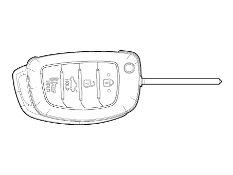
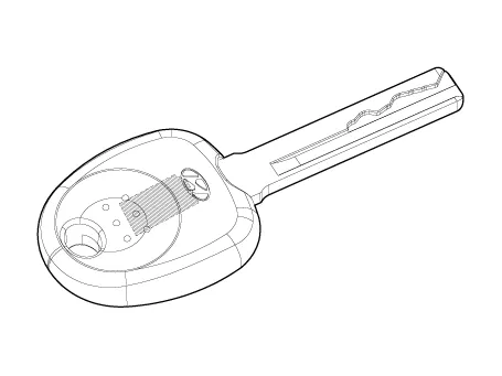
Transponder (Built-in Keys)
The transponder has an advanced encryption algorithm. During the key teaching procedure, the transponder will be programmed with vehicle specific data. The vehicle specific data are written into the transponder memory. The write procedure is once only; therefore, the contents of the transponder can never be modified or changed.
| [Master Folding Key] |
| [Assistant Master Key] |
Antenna Coil
The antenna coil (A) has the following functions.
| – | The antenna coil supplies energy to the transponder. |
| – | The antenna coil receives signal from the transponder. |
| – | The antenna coil sends transponder signal to the IMMOBILIZER. It is located directly in front of the steering handle lock. |

Circuit Diaram
Teaching Procedures1.Key Teaching ProcedureKey teaching must be done after replacing a defective PCM (ECM) or when providing additional keys to the vehicle owner.
Other information:
Hyundai Ioniq (AE) 2017-2022 Service & Repair Manual: A/C Pressure Transducer. Repair procedures
Inspection • Before measuring the pressure of the refriferant line, check whether the refrigerant amount is charged in accordance with the specified charging amount.(Refer to Heating, Ventilation, Air Conditioning - "Specifications")1.
Hyundai Ioniq (AE) 2017-2022 Service & Repair Manual: Components and components location
C
Categories
- Manuals Home
- Hyundai Ioniq Owners Manual
- Hyundai Ioniq Service Manual
- Brake System
- Jump Starting
- Transmission Gear Oil. Repair procedures
- New on site
- Most important about car

Copyright © 2026 www.hioniqae.com - 0.0124