Hyundai Ioniq: Front View Camera System / Description and operation
Blcok Diagram

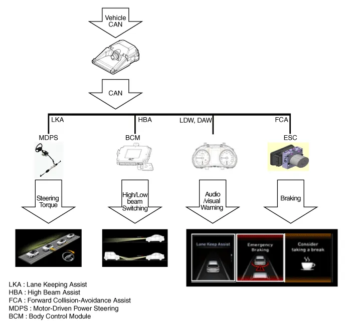
Functions of Front View Camera |
Front View Camera supports the following functions using the information (lane, light source, vehicle and pedestrian) detected by the front view camera and the vehicle's signal information (CAN communication).
1. | Lane Keeping Assist (LKA) : If it is judged that the vehicle leaves the road during driving, the driver is warned of the danger and the steering is controlled in order to prevent the accident. The LKA provides visual / audible warning to the driver if it is determined that the lane departs from the lane in consideration of the lane and road boundary information recognized by the front view camera and whether or not the turn signal lamp operates. However, the front view camera may not operate normally in the limit situation where the lane and road boundaries can not be recognized. |
2. | High Beam Assist (HBA) : High Beam Assist (HBA) controls the operation of the high beam in order to maximize the front visual range while minimizing casting the glare on other drivers at night and under low light conditions. The system uses the front camera to detect whether there is any light source from the front or oncoming vehicle or street light. The system turns off the high beam if there is a light source and turns on the high beam if there is no light source. However, when the front view camera is unable to detect the surrounding situation, the system may not operate normally. |
3. | Forward Collision-Avoidance Assist(FCA) : It warns the driver of risk and controls the braking of the vehicle to prevent collision with front obstacle during driving. (If Sensor Fusion FCA is equipped) THE MFC transmits the recognition information about the forward vehicle/pedestrain to the front radar using CAN communication for FCA operation. |
4. | Driver Attention Warning(DAW) : If it is judged that the driver is inattention driving, the driver is warned to prevent an accident. The DAW analyzes the driving patttern of the driver in consideration of the lane information recognized by the front camera and the information such as the speed/steering angle/brake operation of the vehicle, and gives a visual/audible warning to the driver when it is determined that the driver is inadvertent driving. However, the front camera may not operate normally in a marginal situation where the surroundings can not be recognized. |
The functional requirements of MFC are as follows:
1. | Lane Keeping Assist (LKA) –
| It operates when the LKA function is set and the vehicle speed is over 40mph(60km/h). (LKA Function Setting : LKA Switch ON, USM LKA Mode) |
–
| The lines should be clearly separated, and both lanes should be detected. |
–
| The driver's hand should be placed on the steering wheel and the function is canceled if ignoring the steering force when the LKA function is activated. |
–
| LKA will operate If the lane change is made arbitrarily while the turn signal lamp and emergency light switch are OFF. |
–
| LKA operates at a lane width of 2.8m or more and 4.3m or less. |
–
| If the vehicle crosses more than 40% of the width of the vehicle, it is judged that the lane is deviated to change the lane and the LKA function is canceled. |
–
| In the following cases, the LKA may not operate. |
1) | When driving on a steep curve |
2) | Sudden braking or sudden change of lane |
3) | When the ESC / VSM function is working |
|
2. | High Beam Assist (HBA) 1) | If the light switch is pushed to the instrument panel, the high beam is turned on and the HBA is OFF. |
2) | Operates when the vehicle speed is more than 25mph(40km/h). |
3) | Details of the operation according to the state of the lighting switch during operation of the High Beam Assist (HBA) system are as follows: |
–
| If the light switch is pushed to the instrument panel, the high beam is turned on and the HBA is OFF. |
–
| If the light switch is pulled up with the high beam being turned off, the high beam is turned on and HBA remains ON. (When you release the hand, the switch moves to the center and the high beam is turned off.) |
–
| When the light switch is turned on with the high beam turned on by the HBA, the high beam is turned off and the system is released. |
–
| If you turn the light switch from AUTO to the headlight position, the high beam is turned off and the system is released. |
–
| During HBA operation with high beam is turned on, the headlamp automatically switches to the high beam off state if: |
4) | Detecting the headlights or tail lights of an approaching vehicle |
–
| Detecting the headlights or tail lights of an approaching vehicle |
–
| Detecting the headlights or tail lights of bicycles and motorcycles |
–
| The surroundings are bright enough not to turn on the headlights |
–
| There is a street light or other light in front |
–
| The light switch is not in the AUTO (auto light) position |
–
| The vehicle speed is reduced to 15mph(24km/h) or less |
5) | Even if the HBA operating condition is satisfied, it does not work in the daytime. |
6) | Recognizes the lamp source of the preceding vehicle in normal nighttime environment and automatically high beam turns on or off. |
|
Service Point Target Auto Calibration (SPTAC)When you need calibration :–
Front view camera is removed and mounted–
Replace front view camera with a new one –
Windshield glass changed–
Front view camera coupler of the windshield glass is deformedService Point Target Auto Calibration (SPTAC)Front view camera SPTAC provides the method for the service technician to calibrate the camera by aligning the calibration target (SST: 09890-3V100) with the vehicle on a level ground...
Other information:
ECM Terminal and Input / Output SignalECM Terminal FunctionConnector [C100-A]
Pin No
Description
Connected to
1Injector (Cylinder #3) [Low] control outputInjector (Cylinder #3)2Injector (Cylinder #4) [High] control outputInjector (Cylinder #4)3Injector (Cylinder #3) [Low] control outputInjector (Cylinder #3)4Vehicle speed signal outputCluster5EGR Valve (Motor -)EGR Valve6Sensor power (+5V)Throttle Position Sensor (TPS) 1, 27Sensor power (+5V)EGR Valve8Knock Sensor (KS) signal inputKnock Sensor (KS)9Camshaft Position Sensor (CMPS) [Bank 1 / Exhaust] signal inputCamshaft Position Sensor (CMPS) [Bank 1 / Exhaust]10-11Brake Switch [test] signal inputBrake Switch12Brake Switch [lamp] signal inputBrake Switch13-14-15-16Injector (Cylinder #3) [High] control outputInjector (Cylinder #3)17Injector (Cylinder #1) [High] control outputInjector (Cylinder #1)18Injector (Cylinder #1) [Low] control outputInjector (Cylinder #1)19-20EGR Valve (Motor +)EGR Valve21Sensor shieldKnock Sensor (KS)22Sensor groundKnock Sensor (KS)23-24Sensor groundCamshaft Position Sensor (CMPS) [Bank 1 / Exhaust]25-26-27-28-29-30-31Injector (Cylinder #2) [High] control outputInjector (Cylinder #2) 32-33ETC Motor [-] control outputETC Motor34Sensor groundThrottle Position Sensor (TPS) 1, 235Throttle Position Sensor (TPS) 1 signal inputThrottle Position Sensor (TPS) 136Sensor groundRail Pressure Sensor (RPS)37Rail Pressure Sensor (RPS) signal inputRail Pressure Sensor (RPS)38-39Camshaft Position Sensor (CMPS) [Bank 1 / Intake] signal inputCamshaft Position Sensor (CMPS) [Bank 1 / Intake]40-41-42-43VS-/IP- (Common Ground for VS, IP)Heated Oxygen Sensor [Bank 1 / Sensor 1] 44Rc (Compensative Resistance)Heated Oxygen Sensor [Bank 1 / Sensor 1] 45Sensor groundHeated Oxygen Sensor [Bank 1 / Sensor 2] 46Injector (Cylinder #2) [Low] control outputInjector (Cylinder #2)47-48ETC Motor [+] control outputETC Motor49-50Throttle Position Sensor (TPS) 2 signal inputThrottle Position Sensor (TPS) 251Sensor power (+5V)Rail Pressure Sensor (RPS)52Electrical load signal inputWiper Motor53Sensor groundCamshaft Position Sensor (CMPS) [Bank 1 / Intake]54Sensor groundEGR valve55EGR valve (Feedback signal)EGR valve56-57-58VS+ (NERNST Cell Voltage)Heated Oxygen Sensor [Bank 1 / Sensor 1] 59Rc/Rp (Pump Cell Voltage)Heated Oxygen Sensor [Bank 1 / Sensor 1] 60Heated Oxygen Sensor [Bank 1 / Sensor 2] signal inputHeated Oxygen Sensor [Bank 1 / Sensor 2] Connector [C100-K]
Pin No
Description
Connected to
1ECM GroundChassis Ground2Battery power (B+)Main Relay3ECM GroundChassis Ground4Battery power (B+)Main Relay5ECM GroundChassis Ground6Battery power (B+)Main Relay7Fuel Pressure Control Valve [High] control outputFuel Pressure Control Valve8-9-10Engine Coolant Temperature Sensor (ECTS) signal [EGR Cooler Tube]Engine Coolant Temperature Sensor (ECTS) [EGR Cooler Tube]11Sensor groundEngine Coolant Temperature Sensor (ECTS) [EGR Cooler Tube]12Vehicle speed signal inputIntegrated brake actuation unitSmart key Control Module13-14-15Accelerator Position Sensor (APS) 2 signal inputAccelerator Position Sensor (APS) 216Sensor power (+5V) Accelerator Position Sensor (APS) 217Sensor power (+5V) Manifold Absolute Pressure Sensor (MAPS)18Sensor power (+5V) Accelerator Position Sensor (APS) 119Accelerator Position Sensor (APS) signal inputAccelerator Position Sensor (APS) 120Sensor power (+5V) Crankshaft Position Sensor (CKPS) A/C Pressure Transducer (APT)21-22-23-24Fuel Pump Relay control outputFuel Pump Relay25-26-27-28-29Fuel Pressure Control Valve [Low] control outputFuel Pressure Control Valve30A/C Pressure Transducer (APT) signal inputA/C Pressure Transducer (APT)31-32Crankshaft Position Sensor (CKPS) signal inputCrankshaft Position Sensor (CKPS) 33-34-35-36-37Sensor groundAccelerator Position Sensor (APS) 238Manifold Absolute Pressure Sensor (MAPS) signal inputManifold Absolute Pressure Sensor (MAPS)39Intake Air Temperature Sensor (IATS) signal inputIntake Air Temperature Sensor (IATS)40Sensor groundManifold Absolute Pressure Sensor (MAPS)41Sensor groundAccelerator Position Sensor (APS) 142-43-44Mass Air Flow Sensor (MAFS) signal inputMass Air Flow Sensor (MAFS) 45Sensor groundMass Air Flow Sensor (MAFS) 46Engine Control Relay control outputMain Relay47CVVT Oil control solenoid (OCS) [Bank 1 / Intake] control outputCVVT Oil control solenoid (OCS) [Bank 1 / Intake]48-49-50-51Battery power (B+)Ignition Switch52-53-54Sensor groundCrankshaft Position Sensor (CKPS) 55P-CAN [High]Other control module, Data Link Connector (DLC), Multi-Purpose Check Connetor56H-CAN [High]Other control module, Data Link Connector (DLC), Multi-Purpose Check Connetor57-58Immobilizer communication lineSmart key Control Module59-60Engine Coolant Temperature Sensor (ECTS) signal input [Water Temperature Control Assembly]Engine Coolant Temperature Sensor (ECTS) [Water Temperature Control Assembly]61Sensor groundEngine Coolant Temperature Sensor (ECTS) [Water Temperature Control Assembly]62Fuel Level Sender (FLS) signal inputFuel Level Sender (FLS)63-64Ignition Coil (Cylinder #2) control outputIgnition Coil (Cylinder #2)65Ignition Coil (Cylinder #3) control outputIgnition Coil (Cylinder #3)66-67-68Cooling Fan Relay control outputCooling Fan Relay69-70CVVT Oil Control (OCV) Valve [Bank 1 / Exhaust] control outputCVVT Oil Control Valve (OCV) [Bank 1 / Exhaust] 71- 72- 73Battery power (B+)Battery74- 75Sensor groundA/C Pressure Transducer (APT)76LIN communication signal inputBattery Sensor77P-CAN [Low]Other control module, Data Link Connector (DLC), Multi-Purpose Check Connetor78H-CAN [Low]Other control module, Data Link Connector (DLC), Multi-Purpose Check Connetor79- 80- 81- 82- 838485- 86Ignition Coil (Cylinder #4) control outputIgnition Coil (Cylinder #4)87Ignition Coil (Cylinder #1) control outputIgnition Coil (Cylinder #1)88- 89- 90-91Heated Oxygen Sensor (HO2S) [Bank 1 / Sensor1] Heater control outputHeated Oxygen Sensor (HO2S) [Bank 1 / Sensor 1]92Heated Oxygen Sensor (HO2S) [Bank 1 / Sensor2] Heater control outputHeated Oxygen Sensor (HO2S) [Bank 1 / Sensor 1]93Purge Control Solenoid Valve (PCSV) control outputPurge Control Solenoid Valve (PCSV)94-ECM Terminal Input/Output Signal Connector [C100-A]
Pin No
Description
Condition
Type
Level
1IInjector (Cylinder #3) [Low] control outputRelay OFFDC71VRelay ONMax 1...
High Voltage Shut-off Procedures
•
Be sure to read and follow the "General Safety Information and Caution" before doing any work related with the high voltage system. Failure to follow the safety instructions may result in serious electrical injuries...
Categories
Seat belt warning light

As a reminder to the driver, the seat belt warning light will illuminate and
warning chime will sound for approximately 6 seconds each time you place the Engine
Start/Stop button to the ON position if the seat belt is unfastened.
read more