
Hyundai Ioniq (AE): Intake and Exhaust System / EGR Cooler. Repair procedures
Hyundai Ioniq (AE) 2017-2022 Service & Repair Manual / Engine Mechanical System / Intake and Exhaust System / EGR Cooler. Repair procedures
| Removal and installation |
| 1. | Disconnect the battery negative terminal. |
| 2. | Remove the engine room under cover. (Refer to Engine and Transaxle Assembly - "Engine Room Under Cover") |
| 3. | Loosen the drain plug, and drain the engine coolant. Remove the reservoir cap to help drain the coolant faster. (Refer to Cooling System - "Coolant") |
| 4. | Remove the exhaust manifold. (Refer to Intake and Exhaust System - "Exhaust Manifold") |
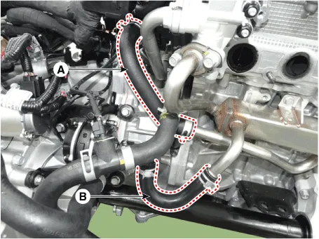
| 5. | Disconnect the EGR cooler hose (A) and EWP water hose (B).
|
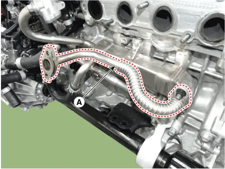
| 6. | Remove the EGR cooler pipe (A).
|
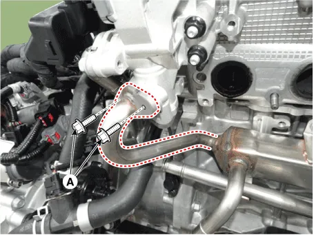
| 7. | Remove the EGR cooler pipe B bolts (A).
|
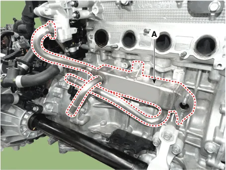
| 8. | Remove the EGR cooler (A).
|
| 9. | Install in the reverse order of removal. |
| 10. | Fill the radiator with coolant and check for leaks. (Refer to Cooling System - "Coolant") |
| 11. | Start engine and check for leaks. |
| 12. | Recheck the coolant level. |
Description and Operation
Components1. Front muffler2. GPF3. Center muffler4. Rear muffler5. Gasket6. Hanger
Other information:
Hyundai Ioniq (AE) 2017-2022 Service & Repair Manual: emperature Control Actuator. Repair procedures
Inspection1.Turn the ignition switch OFF.2.Disconnect the temperature control actuator connector.3.Verify that the temperature control actuator operates to the cool position when connecting 12V to terminal 3 and grounding terminal 7.Verify that the temperature control actuator operates to the warm position when connected in reverse.
Hyundai Ioniq (AE) 2017-2022 Service & Repair Manual: Blower Motor. Repair procedures
Inspection1.Connect the battery voltage and check the blower motor rotation.2.If the blower motor does not operate well, substitute with a known-good blower motor and check for proper operation.3.Replace the blower motor if it is proved that there is a problem with it.
Categories
- Manuals Home
- Hyundai Ioniq Owners Manual
- Hyundai Ioniq Service Manual
- Jump Starting
- Hybrid Control System
- Body (Interior and Exterior)
- New on site
- Most important about car

Copyright В© 2026 www.hioniqae.com - 0.0186