Hyundai Ioniq (AE): Towing / Emergency Towing
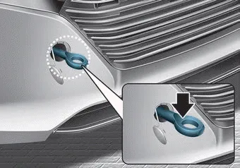
â– Front
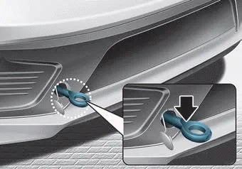
â– Rear
If towing is necessary, we recommend you to have it done by an authorized HYUNDAI dealer or a commercial tow truck service.
If a towing service is not available in an emergency, your vehicle may be temporarily towed using a cable or chain secured to the emergency towing hook at the rear of the vehicle.
Use extreme caution when towing the vehicle with a cable or chain. A driver must be in the vehicle to steer it and operate the brakes.
Towing should be done only on a solid ground for a short distance and at a low speed.
Also, the wheels, axles, power train, steering and brakes must all be in good condition.
Always follow these emergency towing precautions:
- Place the Engine Start/Stop button in the ACC position so the steering wheel is not locked.
- Place the shift lever in N (Neutral).
- Release the parking brake.
- Depress the brake pedal with more force than normal since you will have reduced braking performance.
- More steering effort will be required because the power steering system will be disabled.
- Use a vehicle heavier than your own to tow your vehicle.
- The drivers of both vehicles should communicate with each other frequently.
- Before emergency towing, check that the hook is not broken or damaged.
- Fasten the towing cable or chain securely to the hook.
- Do not jerk the hook. Apply steady and even force.
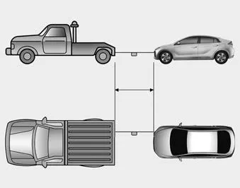
- Use a towing cable or chain less than 16 feet (5 m) long. Attach a white or red cloth (about 12 inches (30 cm) wide) in the middle of the cable or chain for easy visibility.
- Drive carefully so the towing cable or chain remains tight during towing.
- Before towing, check the dual clutch transmission for fluid leaks under your vehicle. If the dual clutch transmission fluid is leaking, flatbed equipment or a towing dolly must be used.
CAUTION
To avoid damage to your vehicle and vehicle components when towing:
- Always pull straight ahead when using the towing hooks. Do not pull from the side or at a vertical angle.
- Do not use the towing hooks to pull a vehicle out of mud, sand or other conditions from which the vehicle cannot be driven out under its own power.
- Limit the vehicle speed to 10 mph (15 km/h) and drive less than 1 mile (1.5 km) when towing to avoid serious damage to the dual clutch transmission.
1. Open the liftgate, and take the towing hooks out from the tool case. â– Front â– Rear 2. Remove the hole cover by pressing the lower part of the cover on the front or rear bumper.
WARNING For your safety, do not touch high voltage cables, connectors and package modules. High voltage components are orange in color. Exposed cables or wires may be visible inside or outside of the vehicle.
Other information:
Hyundai Ioniq (AE) 2017-2022 Service & Repair Manual: Repair procedures
Service Point Target Auto Calibration (SPTAC)When you need calibration :– Front view camera is removed and mounted– Replace front view camera with a new one – Windshield glass changed– Front view camera coupler of the windshield glass is deformedService Point T
Hyundai Ioniq (AE) 2017-2022 Service & Repair Manual: Repair procedures
Removal1.Disconnect the negative (-) battery terminal.2.Remove the tailgate lid trim.(Refer to Body - "TailGate Lid Trim")3.Disconnect the Rear view camera connector (A).4.Remove the Rear view camera assembly after loosening the mounting screws.Installation1.
Categories
- Manuals Home
- Hyundai Ioniq Owners Manual
- Hyundai Ioniq Service Manual
- Jump starting procedure
- Engine Control/Fuel System
- Maintenance
- New on site
- Most important about car
