Hyundai Ioniq: Engine and Transaxle Assembly / Engine and Transaxle Assembly. Repair procedures
| •
| Be sure to read and follow the "General Safety Information and Caution" before doing any work related with the high voltage system. Failure to follow the safety instructions may result in serious electrical injuries. |
| •
| Be sure to read and follow the "High Voltage Shut-off Procedures" before doing any work related with the high voltage system. Failure to follow the safety instructions may result in serious electrical injuries. |
|
| •
| Use fender covers to avoid damaging painted surfaces. |
| •
| To avoid damage, unplug the wiring connectors carefully while holding the connector portion. |
|
| •
| Mark all wiring and hoses to avoid misconnection. |
| •
| To release the fuel system pressure before removing the engine assembly, start the engine with the fuel pump relay removed. and then turn off the ignition switch after engine stops. |
|
| 1. | Shut off the High Voltage circuit. (Refer to General Information - "High Voltage Shutoff Procedure") |
| 2. | Disconnect the battery negative terminal. |
| 3. | Remove the air cleaner assembly. (Refer to Intake and Exhaust System - "Air Cleaner") |
| 4. | Remove the engine room under cover. (Refer to Engine and Transaxle Assembly - "Engine Room Under Cover") |
| 5. | Loosen the drain plug, and drain the engine coolant. Remove the reservoir cap to help drain the coolant faster. (Refer to Cooling System - "Coolant") |
| 6. | Loosen the drain plug, and drain the inverter coolant. Remove the reservoir cap to help drain the coolant faster. (Refer to Hybrid Motor System - "Coolant") |
| 7. | Remove the hybrid power control unit (HPCU). (Refer to Hybrid Control System - "Hybrid Power Control Unit (HPCU)") |
| 8. | Remove the engine control module (ECM) and DCT control module (TCM) (Refer to Engine Control / Fuel System - "Engine Control Module (ECM)") (Refer to Double Clutch Transmission (DCT) System - "DCT Control Module (TCM)") |
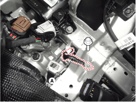
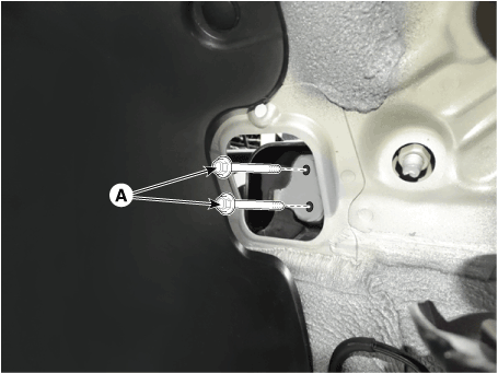
| 9. | Disconnect the wiring harness from the engine room. | (1) | Remove the ground bolt (A). |
| (2) | Disconnect the front harness connector (B). |
| (3) | Disconnect the PCB block (C). |
| (4) | Disconnect the wiring protector (D). |
| (5) | Disconnect the battery positive wirings (E). 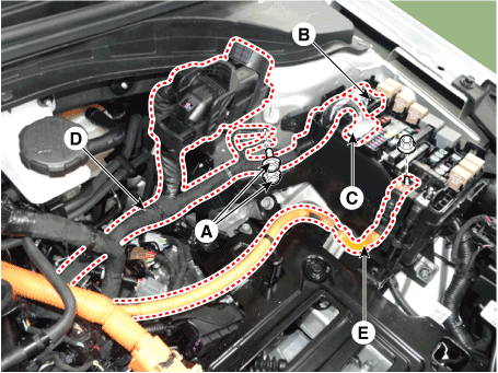
|
|
| 10. | Remove the hybrid power control unit (HPCU) tray. (Refer to Hybrid Control System - "Hybrid Power Control Unit (HPCU)") |
| 11. | Remove the transaxle wire harness connectors and control cable from the transaxle. (Refer to Double Clutch Transmission (DCT) System - "Double Clutch Transmission (DCT)") |
| 12. | Recover the refrigerant and then remove the high pressure pipe and low pressure pipe. (Refer to Heating, Ventilation Air Conditioning - "Compressor") |
| 13. | Disconnect the electric water pump (EWP) coolant hose (A). 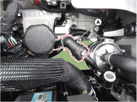
|
| 14. | Disconnect the fuel hose (A) and the purge control solenoid valve (PCSV) hose (B). 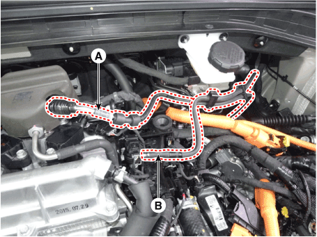
|
| 15. | Disconnect the heater hoses (A). 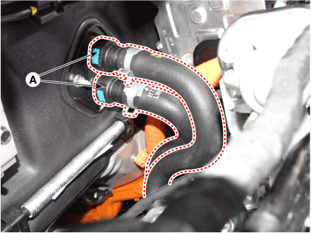
|
| 16. | Disconnect the radiator upper hose (A). 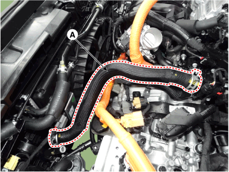
| •
| When installing radiator hoses, install as shown in illustrations. 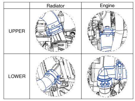
|
|
|
| 17. | Disconnect the radiator lower hose (A). 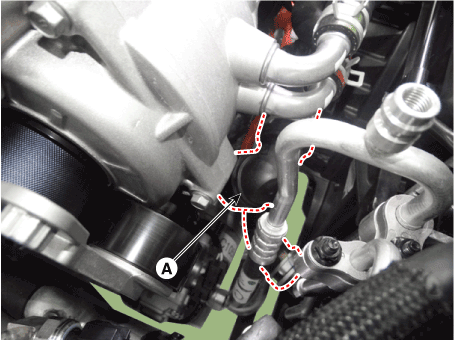
| •
| When installing radiator hoses, install as shown in illustrations.
|
|
| •
| When the radiator lower hose detached, remove the holder clip (A) and then disconnect the quick connector. 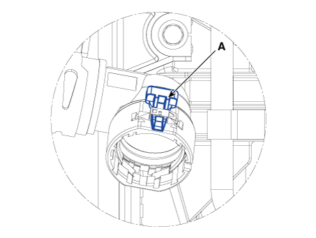
|
|
|
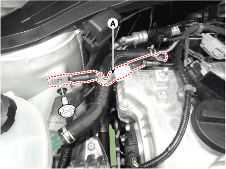
| 18. | Disconnect the hybrid starter generator (HSG) coolant hose (A). 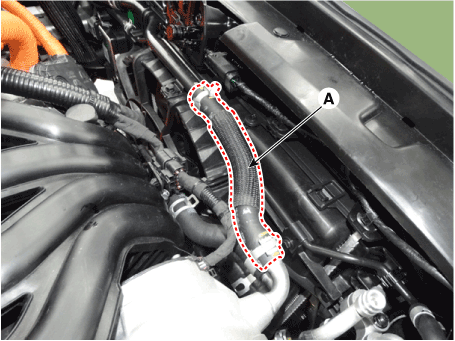
|
| 19. | Disconnect the reservoir tank coolant hose (A). 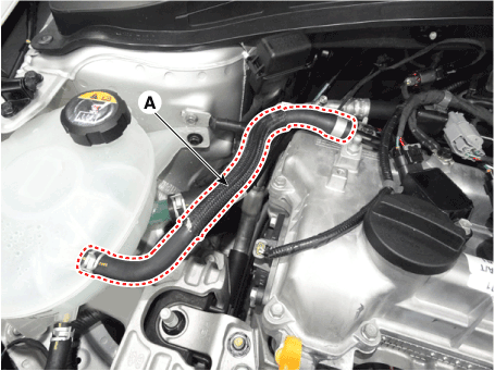
|
| 20. | Disconnect the reservoir tank coolant hose (A). 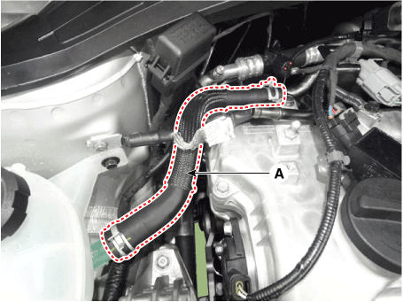
|
| 21. | Remove the front muffler. (Refer to Intake and Exhaust System - "Muffler") |
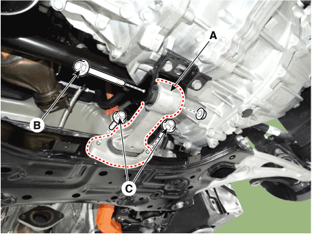
| 22. | Remove the steering U-joint mounting bolts. (Refer to Steering System - "Steering Column and Shaft") |
| 23. | Remove the roll rod bracket (A). Tightening torque Bolt (B) : 107.9 - 127.5 N.m (11.0 - 13.0 kgf.m, 79.6 - 94.0 lb-ft) Bolts (C) : 49.0 - 63.7 N.m (5.0 - 6.5 kgf.m, 36.2 - 47.0 lb-ft) |
|
| 24. | Remove the roll rod mounting support bracket (A). Tightening torque : 49.0 - 68.6 N.m (5.0 - 7.0 kgf.m, 36.2 - 50.6 lb-ft) |
|
| 25. | Support the sub frame with a floor jack, and then remove the sub frame assembly. (Refer to Suspension System - "Sub Frame") |
| 26. | Disconnect the engine ground cable (A). Tightening torque : 10.8 - 13.7 N.m (1.1 - 1.4 kgf.m, 8.0 - 10.1 lb-ft) |
|
| 27. | Remove the engine mounting support bracket (A). Tightening torque : Nut (B) : 88.3 - 107.9 N.m (9.0 - 11.0 kgf.m, 65.1 - 79.6 lb-ft) Bolt (C), Nut (D) : 58.8 - 73.5 N.m (6.0 - 7.5 kgf.m, 43.4 - 54.2 lb-ft) |
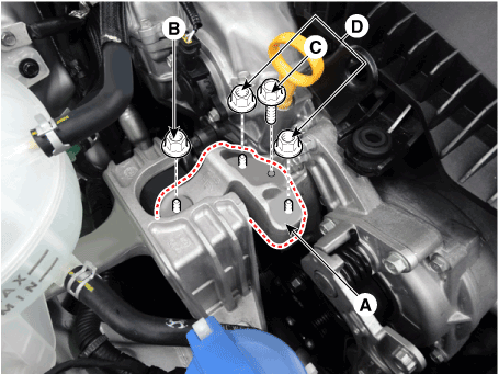
|
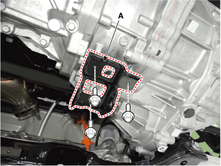
| 28. | Disconnect the transaxle ground cable (A). Tightening torque : 10.8 - 13.7 N.m (1.1 - 1.4 kgf.m, 8.0 - 10.1 lb-ft) |
|
| 29. | Remove the service cover (A). 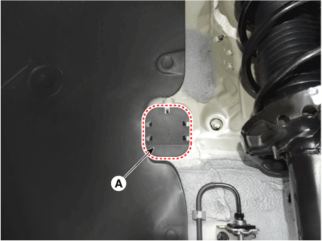
|
| 30. | Remove the transaxle support bracket mounting bolts (A). Tightening torque : 88.3 - 107.9 N.m (9.0 - 11.0 kgf.m, 65.1 - 79.6 lb-ft) |
|
| 31. | Remove the engine and transaxle assembly by lifting vehicle. 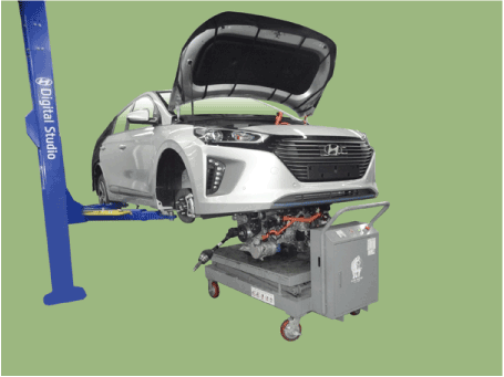
| •
| When remove the engine and transaxle assembly, be careful not to damage any surrounding parts or body components. |
|
|
Installation is in the reverse order of removal.
Add all the necessary fluids and check for leaks. Connect GDS. Check for codes, note, and clear. Recheck.
| •
| Refill engine with engine oil. |
| •
| Refill a transaxle with fluid. |
| •
| Refill an engine radiator and a reservoir tank with coolant. |
| •
| Refill an inverter radiator and a reservoir tank with coolant. |
| •
| Clean battery posts and cable terminals and assemble. |
| •
| Inspect for fuel leakage. |
| –
| After assemble the fuel line, turn on the ignition switch (do not operate the starter) so that the fuel pump runs for approximately two seconds and fuel line pressurizes. |
| –
| Repeat this operation two or three times, then check for fuel leakage at any point in the fuel line. |
| •
| Bleed air from the hybrid motor cooling system. (Refer to Hybrid Motor System - "Coolant") |
| •
| Bleed air from the engine cooling system. |
| –
| Start engine and let it run until it warms up. (until the radiator fan operates 3 or 4 times.) |
| –
| Turn Off the engine. Check the level in the radiator, add coolant if needed. This will allow trapped air to be removed from the cooling system. |
| –
| Put radiator cap on tightly, then run the engine again and check for leaks. |
|
Removal and InstallationRoll Rod Bracket1.Remove the roll rod bracket (A). Tightening torque Bolt (B) :107.9 - 127.5 N.m (11.0 - 13...
Other information:
Replacement1.Remove the front door trim.(Refer to Front Door - "Front Door Trim")2.Remove the front door belt inside weatherstrip (A).3.To install, reverse the removal procedure.
•
When installing, install it by first contacting the inside part (basis point of assembly) of arrow to door frame...
Replacement
•
When a DTC related to MDPS motor occurs, check the connectors and wiring. If no problem is found, replace the motor.
•
Be sure to check the last two digits of the constant in the barcode of new MDPS motor before replacing the motor...
Categories
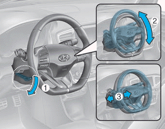
Adjust the steering wheel so it points toward your chest, not toward your face.
Make sure you can see the instrument cluster warning lights and gauges. After adjusting,
push the steering wheel both up and down to be certain it is locked in position.
Always adjust the position of the steering wheel before driving.
WARNING
NEVER adjust the steering wheel while driving. This may cause loss of vehicle
control resulting in an accident.
read more


 Engine Mounting. Repair procedures
