Hyundai Ioniq (AE): Engine Control System / Engine Control Module (ECM). Repair procedures
| •
| When replacing the ECM, the vehicle equipped with the immobilizer must be performed procedure as below. |
[In the case of installing used ECM] | 1) | Perform "ECM Neutral mode" procedure with GDS. (Refer to Body Electrical System - "Immobilizer System") |
| 2) | After finishing "ECM Neutral mode", perform "Key teaching" procedure with GDS. (Refer to Body Electrical System - "Immobilizer System") |
[In the case of installing new ECM] | –
| Perform "Key teaching" procedure with GDS. (Refer to Body Electrical System - "Immobilizer System") |
|
| •
| When replacing the ECM, the vehicle equipped with the smart key system (Button start) must be performed procedure as below. |
[In the case of installing used ECM] | 1) | Perform "ECM Neutral mode" procedure with GDS. (Refer to Body Electrical System - "Smart Key") |
| 2) | After finishing "ECM Neutral mode", insert the key (or press the start button) and turn it to the IGN ON and OFF position. Then the ECM learns the smart key information automatically. |
[In the case of installing new ECM] | –
| Insert the key (or press the start button) and turn it to the IGN ON and OFF position. Then the ECM learns the smart key information automatically. |
|
| 1. | Turn ignition switch OFF and disconnect the negative (-) battery cable. |
| 2. | Disconnect the TCM Connector (A). |
| 3. | Disconnect the ECM Connector (B). 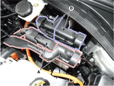
|
| 4. | Remove the ECM (C) from the bracket after removing the screw (A) and nut (B). 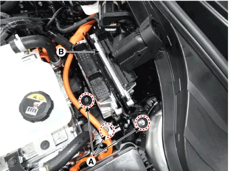
|
| 5. | Remove ECM (B) from the ECM and TCM bracket after loosening the bolt and nut (A). 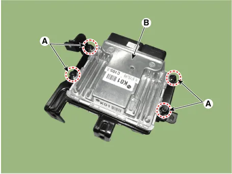
|
| •
| When replacing the ECM, the vehicle equipped with the immobilizer must be performed procedure as below. |
[In the case of installing used ECM] | 1) | Perform "ECM Neutral mode" procedure with GDS. (Refer to Body Electrical System - "Immobilizer System") |
| 2) | After finishing "ECM Neutral mode", perform "Key teaching" procedure with GDS. (Refer to Body Electrical System - "Immobilizer System") |
[In the case of installing new ECM] | –
| Perform "Key teaching" procedure with GDS. (Refer to Body Electrical System - "Immobilizer System") |
|
| •
| When replacing the ECM, the vehicle equipped with the smart key system (Button start) must be performed procedure as below. |
[In the case of installing used ECM] | 1) | Perform "ECM Neutral mode" procedure with GDS. (Refer to Body Electrical System - "Smart Key") |
| 2) | After finishing "ECM Neutral mode", insert the key (or press the start button) and turn it to the IGN ON and OFF position. Then the ECM learns the smart key information automatically. |
[In the case of installing new ECM] | –
| Insert the key (or press the start button) and turn it to the IGN ON and OFF position. Then the ECM learns the smart key information automatically. |
|
| 1. | Install in the reverse order of removal. ECM Installation nut : 9.8 - 11.8 N.m (1.0 - 1.2 kgf.m, 7.2 - 8.7 lb-ft) ECM Bracket installation bolt / nut : 7.8 - 11.8 N.m (0.8 - 1.2 kgf.m, 5.8 - 8.7 lb-ft) |
|
| ECM Problem Inspection Procedure |
| 1. | TEST ECM GROUND CIRCUIT : Measure resistance between ECM and chassis ground using the backside of ECM harness connector as ECM side check point. If the problem is found, repair it. Specification : Below 1Ω |
|
| 2. | TEST ECM CONNECTOR : Disconnect the ECM connector and visually check the ground terminals on ECM side and harness side for bent pins or poor contact pressure. If the problem is found, repair it. |
| 3. | If problem is not found in Step 1 and 2, the ECM could be faulty. If so, make sure there were no DTC's before swapping the ECM with a new one, and then check the vehicle again. If DTC's were found, examine this first before swapping ECM. |
| 4. | RE-TEST THE ORIGINAL ECM : Install the original ECM (may be broken) into a known-good vehicle and check the vehicle. If the problem occurs again, replace the original ECM with a new one. If problem does not occur, this is intermittent problem. (Refer to "Intermittent Problem Inspection Procedure" in Basic Inspection Procedure) |
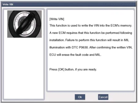
VIN Programming Procedure
VIN (Vehicle Identification Number) is a number that has the vehicle's information (Maker, Vehicle Type, Vehicle Line/Series, Body Type, Engine Type, Transmission Type, Model Year, Plant Location and so forth. For more information, please refer to the group "GI" in this SERVICE MANUAL). When replacing an ECM, the VIN must be programmed in the ECM. If there is no VIN in ECM memory, the fault code (DTC P0630) is set.
| •
| The programmed VIN cannot be changed. When writing the VIN, confirm the VIN carefully |
|
| 1. | Select "VIN Writing" function in "Vehicle S/W Management". |
| 2. | Select "Write VIN" in "ID Register". 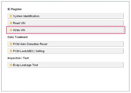
|
| 3. | Input the VIN. | •
| Before inputing the VIN, confirm the VIN again because the programmed VIN cannot be changed. |
|
|
| 4. | Turn the ignition switch OFF, then back ON. |
ECM Terminal and Input / Output SignalECM Terminal FunctionConnector [C100-A]
Pin No
Description
Connected to
1Injector (Cylinder #3) [Low] control outputInjector (Cylinder #3)2Injector (Cylinder #4) [High] control outputInjector (Cylinder #4)3Injector (Cylinder #3) [Low] control outputInjector (Cylinder #3)4Vehicle speed signal outputCluster5EGR Valve (Motor -)EGR Valve6Sensor power (+5V)Throttle Position Sensor (TPS) 1, 27Sensor power (+5V)EGR Valve8Knock Sensor (KS) signal inputKnock Sensor (KS)9Camshaft Position Sensor (CMPS) [Bank 1 / Exhaust] signal inputCamshaft Position Sensor (CMPS) [Bank 1 / Exhaust]10-11Brake Switch [test] signal inputBrake Switch12Brake Switch [lamp] signal inputBrake Switch13-14-15-16Injector (Cylinder #3) [High] control outputInjector (Cylinder #3)17Injector (Cylinder #1) [High] control outputInjector (Cylinder #1)18Injector (Cylinder #1) [Low] control outputInjector (Cylinder #1)19-20EGR Valve (Motor +)EGR Valve21Sensor shieldKnock Sensor (KS)22Sensor groundKnock Sensor (KS)23-24Sensor groundCamshaft Position Sensor (CMPS) [Bank 1 / Exhaust]25-26-27-28-29-30-31Injector (Cylinder #2) [High] control outputInjector (Cylinder #2) 32-33ETC Motor [-] control outputETC Motor34Sensor groundThrottle Position Sensor (TPS) 1, 235Throttle Position Sensor (TPS) 1 signal inputThrottle Position Sensor (TPS) 136Sensor groundRail Pressure Sensor (RPS)37Rail Pressure Sensor (RPS) signal inputRail Pressure Sensor (RPS)38-39Camshaft Position Sensor (CMPS) [Bank 1 / Intake] signal inputCamshaft Position Sensor (CMPS) [Bank 1 / Intake]40-41-42-43VS-/IP- (Common Ground for VS, IP)Heated Oxygen Sensor [Bank 1 / Sensor 1] 44Rc (Compensative Resistance)Heated Oxygen Sensor [Bank 1 / Sensor 1] 45Sensor groundHeated Oxygen Sensor [Bank 1 / Sensor 2] 46Injector (Cylinder #2) [Low] control outputInjector (Cylinder #2)47-48ETC Motor [+] control outputETC Motor49-50Throttle Position Sensor (TPS) 2 signal inputThrottle Position Sensor (TPS) 251Sensor power (+5V)Rail Pressure Sensor (RPS)52Electrical load signal inputWiper Motor53Sensor groundCamshaft Position Sensor (CMPS) [Bank 1 / Intake]54Sensor groundEGR valve55EGR valve (Feedback signal)EGR valve56-57-58VS+ (NERNST Cell Voltage)Heated Oxygen Sensor [Bank 1 / Sensor 1] 59Rc/Rp (Pump Cell Voltage)Heated Oxygen Sensor [Bank 1 / Sensor 1] 60Heated Oxygen Sensor [Bank 1 / Sensor 2] signal inputHeated Oxygen Sensor [Bank 1 / Sensor 2] Connector [C100-K]
Pin No
Description
Connected to
1ECM GroundChassis Ground2Battery power (B+)Main Relay3ECM GroundChassis Ground4Battery power (B+)Main Relay5ECM GroundChassis Ground6Battery power (B+)Main Relay7Fuel Pressure Control Valve [High] control outputFuel Pressure Control Valve8-9-10Engine Coolant Temperature Sensor (ECTS) signal [EGR Cooler Tube]Engine Coolant Temperature Sensor (ECTS) [EGR Cooler Tube]11Sensor groundEngine Coolant Temperature Sensor (ECTS) [EGR Cooler Tube]12Vehicle speed signal inputIntegrated brake actuation unitSmart key Control Module13-14-15Accelerator Position Sensor (APS) 2 signal inputAccelerator Position Sensor (APS) 216Sensor power (+5V) Accelerator Position Sensor (APS) 217Sensor power (+5V) Manifold Absolute Pressure Sensor (MAPS)18Sensor power (+5V) Accelerator Position Sensor (APS) 119Accelerator Position Sensor (APS) signal inputAccelerator Position Sensor (APS) 120Sensor power (+5V) Crankshaft Position Sensor (CKPS) A/C Pressure Transducer (APT)21-22-23-24Fuel Pump Relay control outputFuel Pump Relay25-26-27-28-29Fuel Pressure Control Valve [Low] control outputFuel Pressure Control Valve30A/C Pressure Transducer (APT) signal inputA/C Pressure Transducer (APT)31-32Crankshaft Position Sensor (CKPS) signal inputCrankshaft Position Sensor (CKPS) 33-34-35-36-37Sensor groundAccelerator Position Sensor (APS) 238Manifold Absolute Pressure Sensor (MAPS) signal inputManifold Absolute Pressure Sensor (MAPS)39Intake Air Temperature Sensor (IATS) signal inputIntake Air Temperature Sensor (IATS)40Sensor groundManifold Absolute Pressure Sensor (MAPS)41Sensor groundAccelerator Position Sensor (APS) 142-43-44Mass Air Flow Sensor (MAFS) signal inputMass Air Flow Sensor (MAFS) 45Sensor groundMass Air Flow Sensor (MAFS) 46Engine Control Relay control outputMain Relay47CVVT Oil control solenoid (OCS) [Bank 1 / Intake] control outputCVVT Oil control solenoid (OCS) [Bank 1 / Intake]48-49-50-51Battery power (B+)Ignition Switch52-53-54Sensor groundCrankshaft Position Sensor (CKPS) 55P-CAN [High]Other control module, Data Link Connector (DLC), Multi-Purpose Check Connetor56H-CAN [High]Other control module, Data Link Connector (DLC), Multi-Purpose Check Connetor57-58Immobilizer communication lineSmart key Control Module59-60Engine Coolant Temperature Sensor (ECTS) signal input [Water Temperature Control Assembly]Engine Coolant Temperature Sensor (ECTS) [Water Temperature Control Assembly]61Sensor groundEngine Coolant Temperature Sensor (ECTS) [Water Temperature Control Assembly]62Fuel Level Sender (FLS) signal inputFuel Level Sender (FLS)63-64Ignition Coil (Cylinder #2) control outputIgnition Coil (Cylinder #2)65Ignition Coil (Cylinder #3) control outputIgnition Coil (Cylinder #3)66-67-68Cooling Fan Relay control outputCooling Fan Relay69-70CVVT Oil Control (OCV) Valve [Bank 1 / Exhaust] control outputCVVT Oil Control Valve (OCV) [Bank 1 / Exhaust] 71- 72- 73Battery power (B+)Battery74- 75Sensor groundA/C Pressure Transducer (APT)76LIN communication signal inputBattery Sensor77P-CAN [Low]Other control module, Data Link Connector (DLC), Multi-Purpose Check Connetor78H-CAN [Low]Other control module, Data Link Connector (DLC), Multi-Purpose Check Connetor79- 80- 81- 82- 838485- 86Ignition Coil (Cylinder #4) control outputIgnition Coil (Cylinder #4)87Ignition Coil (Cylinder #1) control outputIgnition Coil (Cylinder #1)88- 89- 90-91Heated Oxygen Sensor (HO2S) [Bank 1 / Sensor1] Heater control outputHeated Oxygen Sensor (HO2S) [Bank 1 / Sensor 1]92Heated Oxygen Sensor (HO2S) [Bank 1 / Sensor2] Heater control outputHeated Oxygen Sensor (HO2S) [Bank 1 / Sensor 1]93Purge Control Solenoid Valve (PCSV) control outputPurge Control Solenoid Valve (PCSV)94-ECM Terminal Input/Output Signal Connector [C100-A]
Pin No
Description
Condition
Type
Level
1IInjector (Cylinder #3) [Low] control outputRelay OFFDC71VRelay ONMax 1.
Other information:
Inspection1.Connect the battery voltage and check the blower motor rotation.2.If the blower motor does not operate well, substitute with a known-good blower motor and check for proper operation.3.Replace the blower motor if it is proved that there is a problem with it.
General Safety Information and CautionBe careful of the following precautions when driving the vehicle using the smart cruise control system.
•
The smart cruise control system may have limits in detecting distance to the vehicle ahead due to road and traffic conditions.


