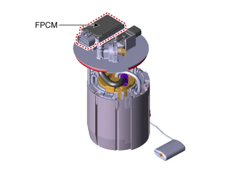
Hyundai Ioniq (AE): Fuel Delivery System / Fuel Pump Control Module (FPCM). Description and operation
| Description |
| Operation |
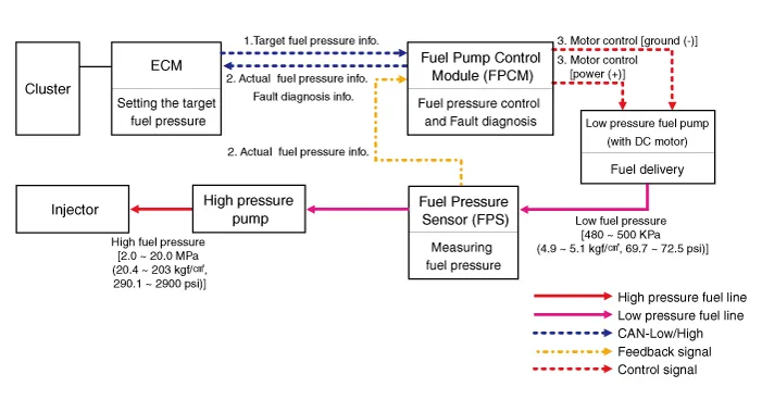
| 1. | The ECM provides target fuel pressure information to the FPCM via CAN network. |
| 2. | The FPS provides the FPCM with actual pressure information of the low pressure fuel line between the low and high pressure fuel pumps, and the FPCM forwards the information to the ECM.Also, the FPCM diagnoses faults in the FPCM, fuel pump motor and FPS and then provides the diagnosis information to the ECM. |
| 3. | The FPCM compares the actual fuel pressure information measured by the FPS with the target fuel pressure information provided by the ECM and controls the voltage that is provided to the low pressure fuel pump motor.The FPCM keeps regulating fuel flow rate by controlling the low pressure fuel pump, depending on engine speed (rpm) and vehicle loads. |
Removal 1.Turn the ignition seitch OFF and disconnect the battery negative (-) cable. 2.Disconnect the accelerator position snesor connector (A).3.Remove the installation nut (A), and then remove the accelerator pedal module.
Circuit DiagramFuel Pressure Control Module (FPCM) Terminal And Input/Output signalFPCM Terminal Function Pin No Discription Connected to 1Fuel sender groundFuel Pump2Fuel pressure sensor (FPS) signal inputFuel Pressure Sensor (FPS)3Fuel pressure sensor (FPS) ground (-)Fuel Pressure Sensor (FPS)4GroundChassis Ground5CAN [Low]ECM6Fuel sender signalFuel Pump7--8Fuel pressure sensor (FPS) Power supply (+5V)Fuel Pressure Sensor (FPS)9CAN [High]ECM10Battery power (B+)Fuel Pump Relay
Other information:
Hyundai Ioniq (AE) 2017-2022 Service & Repair Manual: General safety information and caution
Safety PrecautionPrecautions To Take Before Servicing High Voltage System • Since hybrid vehicles contain a high voltage battery, if the high voltage system or vehicles are handled incorrectly, this might lead to a serious accidents like electric shock and electric leakage.
Hyundai Ioniq (AE) 2017-2022 Service & Repair Manual: Special service tools
Special Service Tools Tool Name / Number Illustration Description LKA Compensator(09964-C1100)Used for compensating front view camera unitBCW Sensor Correction Tool Set(09958-3T500)Used to correct the blind-spot radar unit.
Categories
- Manuals Home
- Hyundai Ioniq Owners Manual
- Hyundai Ioniq Service Manual
- Jump starting procedure
- Body (Interior and Exterior)
- Engine Control/Fuel System
- New on site
- Most important about car
