Hyundai Ioniq (AE): Exhaust Emission Control System / GPF (Gasoline Particulate Filter). Repair procedures
Hyundai Ioniq (AE) 2017-2022 Service & Repair Manual / Engine Electrical System / Exhaust Emission Control System / GPF (Gasoline Particulate Filter). Repair procedures
| GPF Regeneration |
This procedures is to forcibly regenerate the GPF with scan tool when the GPF doesn't have been regenerated during driving. For example, if the vehicle has repeated "Low speed driving" or "Short distance driving", the GPF regeneration procedure cannot be proceeded because "Regeneration Mode" doesn't made.
|

Forcibly Regeneration Condition
| – | Engine coolant temperature : about 70°C |
| – | Engine at idle |
| – | P-range (A/T) or Neutral (M/T) |
| – | Normal battery voltage |
| – | Electrical fully load ON (A/C ON if equipped, Blower ON with maximum speed, Head Lamp ON, Wiper ON, Other Lamps ON, etc.). |
| 1. | Turn ignition switch OFF. |
| 2. | Connect a GDS to Data Link Connector (DLC). |
| 3. | Turn ignition switch ON. |
| 4. | Select "Vehicle, Model year, Engine, System". |
| 5. | Start engine at idle and P-range (A/T) or neutral (M/T). |
| 6. | Apply electrical fully load to the vehicle (A/C ON, Blower ON with maximum speed, Head Lamp ON, Wiper ON, and Other Lamps ON, etc.). |
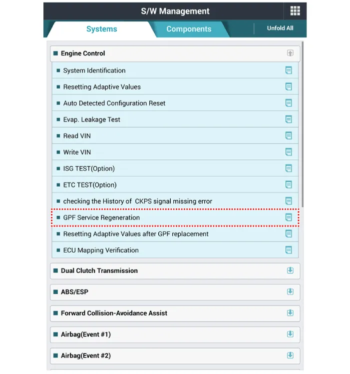
| 7. | Select "Vehicle S/W Management". |
| 8. | Select "GPF Service Regeneration".
|


| Removal |
| 1. | Turn ignition switch OFF and disconnect the battery negative (-) terminal. |
| 2. | Lift the vehicle. |
| 3. | Remove the exhaust gas temperature sensor (EGTS) #1, #2. (Refer to Engine Control / Fuel System - "Exhaust Gas Temperature Sensor (EGTS)") |
| 4. | Remove the GPF (B) after removing the installation nuts (A).
|

| Installation |
| 1. | Install in the reverse order of removal.
|

| Replacement |
|
| 1. | Turn ignition switch OFF. |
| 2. | Connect a GDS to Data Link Connector (DLC). |
| 3. | Turn ignition switch ON. |
| 4. | Select "Vehicle, Model year, Engine, System". |
| 5. | Start engine at idle and P-range (A/T) or neutral (M/T). |
| 6. | Apply electrical fully load to the vehicle (A/C ON, Blower ON with maximum speed, Head Lamp ON, Wiper ON, and Other Lamps ON, etc.). |
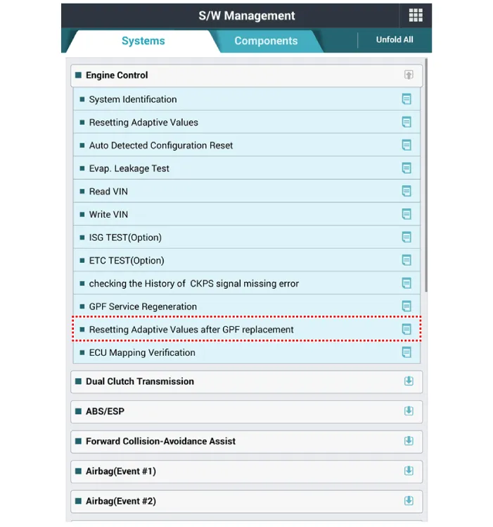
| 7. | Select "Vehicle S/W Management". |
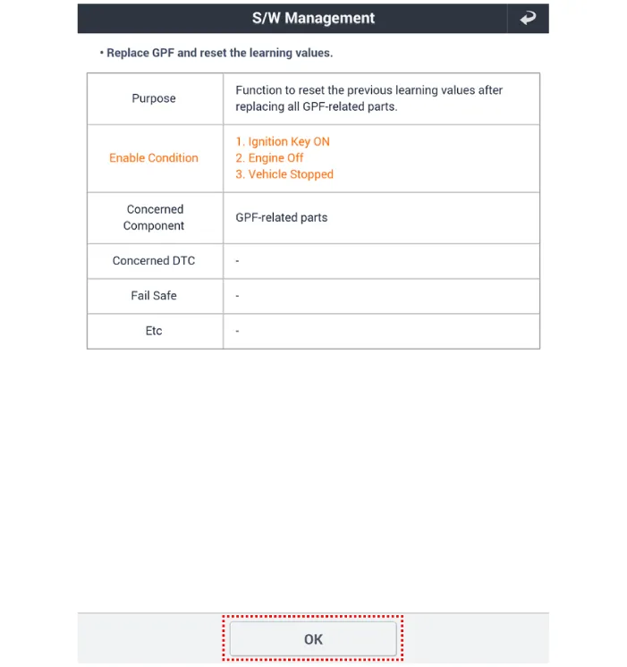
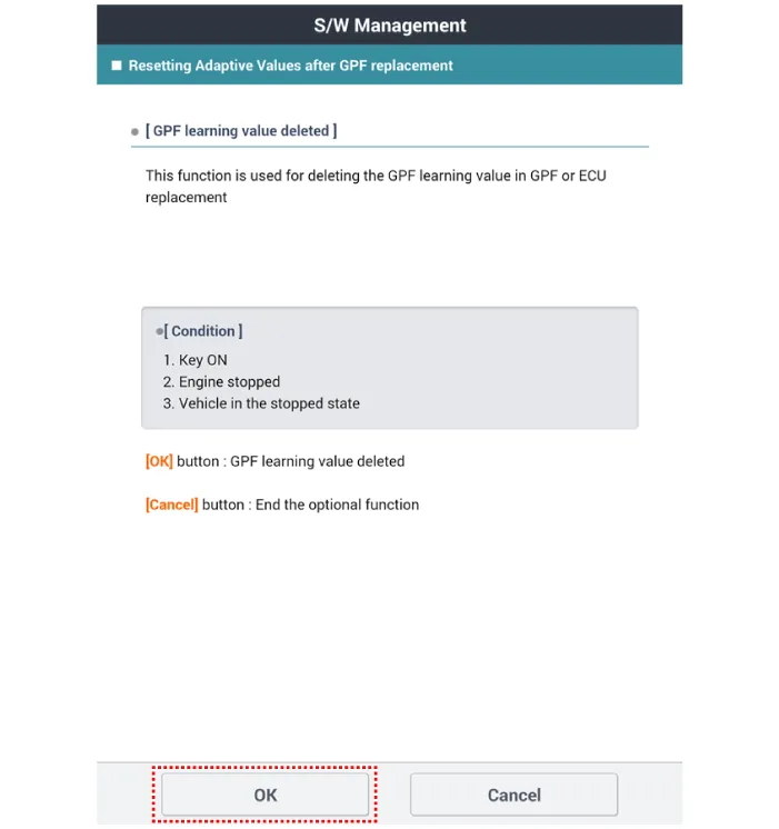
| 8. | Select "Resetting Adaptive Values after GPF replacement".
|
Schematic Diagram
Other information:
Hyundai Ioniq (AE) 2017-2022 Service & Repair Manual: Auto Defogging Sensor. Description and operation
DescriptionThe auto defogging sensor is installed on the front window glass. The sensor judges and sends signal if moisture occurs to blow out wind for defogging. The air conditioner control module receives signal from the sensor and restrains moisture and eliminate defog by controlling the intake actuator, A/C, auto defogging actuator, blower moto
Hyundai Ioniq (AE) 2017-2022 Service & Repair Manual: Mode Control Actuator. Components and components location
C
Categories
- Manuals Home
- Hyundai Ioniq Owners Manual
- Hyundai Ioniq Service Manual
- Hybrid Control System
- Jump Starting
- Jump starting procedure
- New on site
- Most important about car

Copyright © 2026 www.hioniqae.com - 0.0175