Hyundai Ioniq (AE): High Voltage Battery System / Inspection
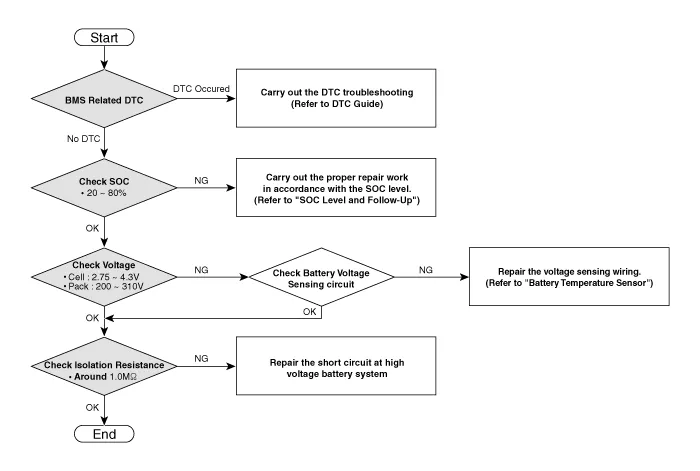
[Battery Pack Assembly Troubleshooting Chart]
| •
| For SOC check, refer to "SOC Inspection" |
| •
| For voltage check, refer to "Battery Voltage Inspection" |
| •
| For battery voltage sensing circuit, refer to "Voltage Sensing Circuit Inspection" |
| •
| For isolation resistance check, refer to "Isolation Resistance Inspection" |
|
[SOC Level and Follow-up]
SOC
| Symptom
| Warning Lamp
| Follow-up
|
MIL
| Service
| Fuel
|
| | -
| -
| -
|
|
10 - 15%
| | •
| Motor torque limite (Acceleration delay) |
| -
| -
| ON
| | •
| Refuel and check the SOC again |
|
ON
| -
| -
| | •
| Repair the MIL or Service Lamp related system |
| •
| Charge the battery by starting the engine |
|
ON
| ON
| -
|
-
| ON
| -
|
On
| ON
| ON
|
5 - 10%
| | -
| -
| ON
| | •
| Refuel and check the SOC again |
|
ON
| -
| -
| | •
| Repair the MIL or Service Lamp related system |
| •
| Charge the battery by starting the engine |
|
ON
| ON
| -
|
-
| ON
| -
|
ON
| ON
| ON
|
0 - 5%
| | ON
| -
| -
| | •
| Repair the MIL or Service Lamp related system |
| •
| Start the engine with GDS to charge the battery |
|
ON
| ON
| -
|
-
| ON
| -
|
ON
| ON
| ON
|
0%
| ON
| -
| -
| | •
| Repair the MIL or Service Lamp related system |
| •
| If necessary, Replace Battery Pack |
|
[SOC Inspection]
| 1. | Connect the GDS to the Data Link Connector (DLC). |
| 2. | Turn the ignition switch ON. |
| 3. | Check the SOC in GDS service data. 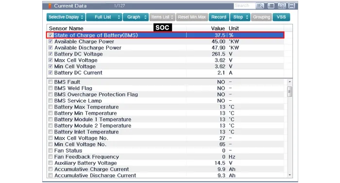
|
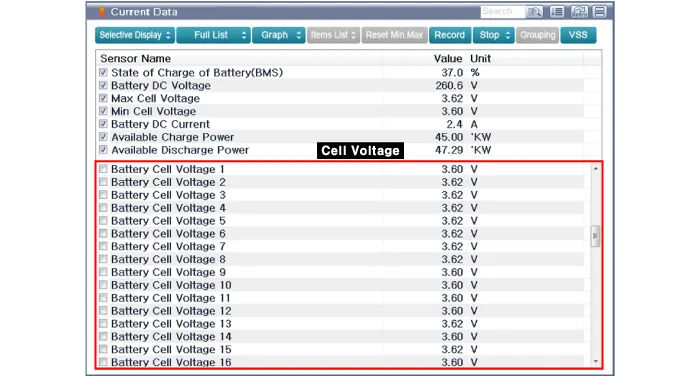
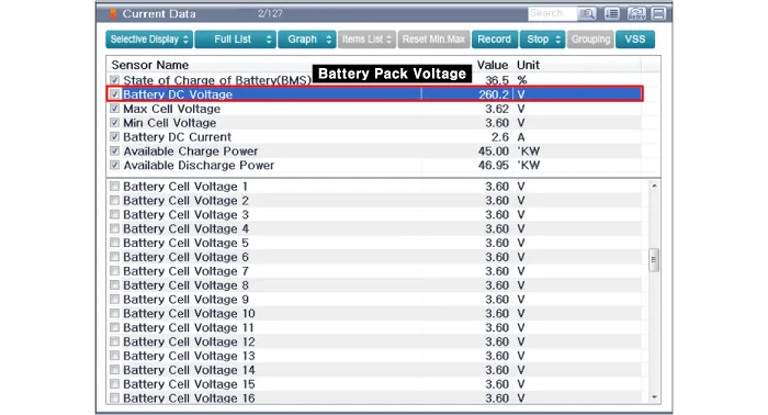
[Battery Voltage Inspection]
| 1. | Connect the GDS to the Data Link Connector (DLC). |
| 2. | Turn the ignition switch ON. |
| 3. | Check the cell and pack voltage in GDS service data. Cell Voltage : 2.5 - 4.3V Pack Voltage : 180 - 300V |
|
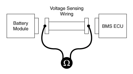
[Voltage Sensing Circuit Inspection]
| 1. | Shut off the high voltage circuit. (Refer to "High Voltage Shutoff Precedure") |
| 2. | Remove the battery temperature sensor. (Refer to "Battery Temperature Sensor") |
| 3. | Check the continuity of the wiring between the harness connectors of the module and BMS ECU. Specification : below 1Ω |
|
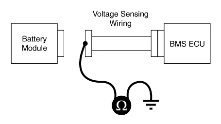
| 4. | Connect the harness connectors to the BMS ECU. |
| 5. | For checking the short circuit to ground, measure resistance between the module harness connectors and chassis ground. Specification : 1 MΩ or higher |
|
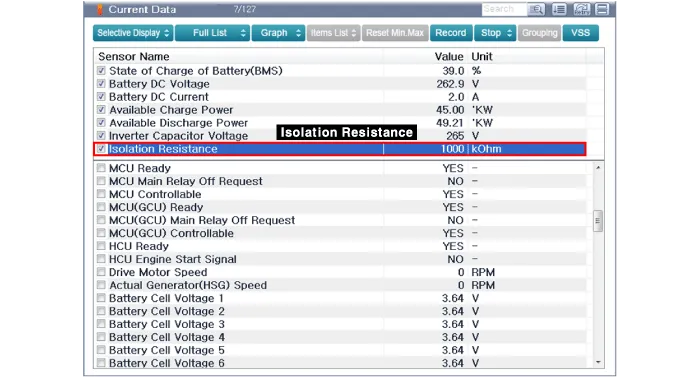
[Isolation Resistance Inspection]
| 1. | Connect the GDS to the Data Link Connector (DLC). |
| 2. | Turn the ignition switch ON. |
| 3. | Check the isolation resistance in GDS service data. Isolation Resistance : Around 1.0 MΩ |
|
SpecificationBattery Pack Assemblyâ–· Type : LiPB (Lithium ion Polymer Battery), Pouch typeâ–· Specification[General Specification]
Item
Specification
Remarks
Number of Cells 16 Cells x 4 Modules 1 Cells = 3.
Removal
•
Be sure to read and follow the "General Safety Information and Caution" before doing any work related with the high voltage system.
Other information:
System Block DiagramComponent Parts and Function Outline
Component part
Function
Vehicle-speed sensor, ESP/ABS Control ModuleConverts vehicle speed to pulse.VCUReceives signals from sensor and control switches.
Trouble Symptom ChartsTrouble Symptom 1Trouble Symptom 2
Trouble symptom
Probable cause
Remedy
The set vehicle speed varies greatly upward or downward"Surging" (repeated alternating acceleration and deceleration) occurs after settingMalfunction of the vehicle speed se

