Hyundai Ioniq (AE): Power Door Locks / Power Door Lock Module. Repair procedures
| Inspection |
|

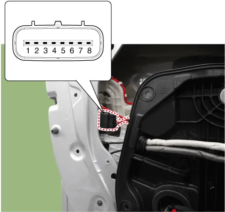
| 1. | Remove the front door trim. (Refer to Body - "Front Door Trim") |
| 2. | Remove the front door module. (Refer to Body - "Front Door Module") |
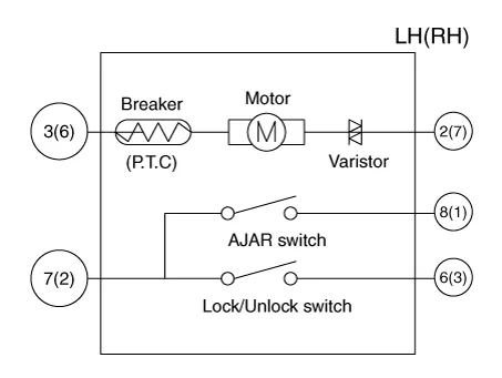
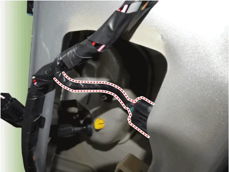
| 3. | Disconnect the connector from the actuator.
| |||||||||||||||||||||||||||||
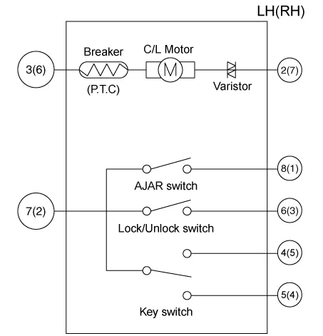
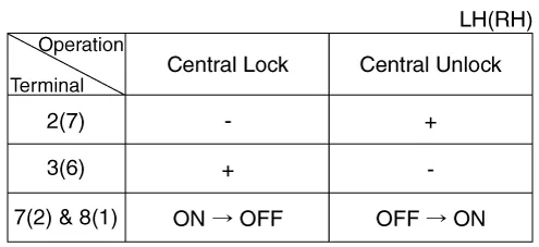
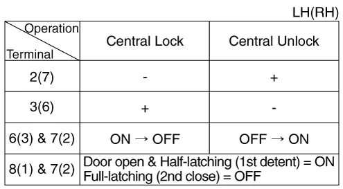
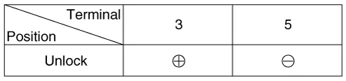
| 4. | Check actuator operation by connecting power and ground according to the table. To prevent damage to the actuator, apply battery voltage only momentarily.
|
| 1. | Remove the rear door trim. (Refer to Body - "Rear Door Trim") |
| 2. | Remove the rear door module. (Refer to Body - "Rear Door Module") |
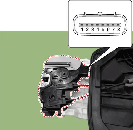
| 3. | Disconnect the connectors from the actuator.
| |||||||||||||||||||||||||||||
| 4. | Check actuator operation by connecting power and ground according to the table. To prevent damage to the actuator, apply battery voltage only momentarily.
|
| 1. | Remove the tailgate lid trim. (Refer to Body - "Tailgate Lid Trim") |
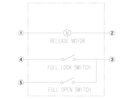
| 2. | Disconnect the connector from the actuator
|

| 3. | Check actuator operation by connecting power and ground according to the table. To prevent damage to the actuator, apply battery voltage only momentarily.
|
| 4. | Checking the trunk of the vehicle power option power refers to the tailgate lock module. |
Conponents1. Door lock/unlock knob cable2. Door inside handle cable3. Door Latch
InspectionPower Door Lock Switch Inspection1.Check for continuity between the terminals. If there is an abnormality, replace the switch.Removal • Be careful not to scratch the door trim and other parts.
Other information:
Hyundai Ioniq (AE) 2017-2022 Service & Repair Manual: Repair procedures
Removal1.Disconnect the negative (-) battery terminal.2.Remove the tailgate lid trim.(Refer to Body - "TailGate Lid Trim")3.Disconnect the Rear view camera connector (A).4.Remove the Rear view camera assembly after loosening the mounting screws.Installation1.
Hyundai Ioniq (AE) 2017-2022 Service & Repair Manual: Description and operation
Cruise ControlThe cruise control system is engaged by the cruise "ON/OFF" main switch located on right of steering wheel column. The system has the capability to cruise, coast, accelerate and resume speed.It also has a safety interrupt, engaged upon depressing brake or shifting select lever.
Categories
- Manuals Home
- Hyundai Ioniq Owners Manual
- Hyundai Ioniq Service Manual
- Description and operation
- Troubleshooting
- DCT(Dual Clutch Transmission) System
- New on site
- Most important about car
