Hyundai Ioniq (AE): Power Door Mirrors / Power Door Mirror Assembly. Repair procedures
Hyundai Ioniq (AE) 2017-2022 Service & Repair Manual / Body Electrical System / Power Door Mirrors / Power Door Mirror Assembly. Repair procedures
| Inspection |
| 1. | Disconnect the negative (-) battery terminal. |
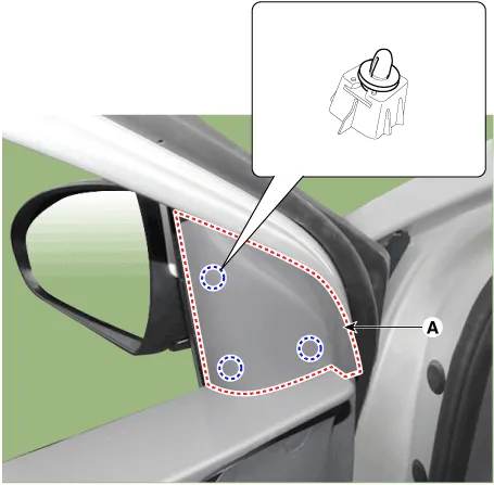
| 2. | Remove the front door quadrant inner cover (A).
|
| 3. | Disconnect the power door mirror connector from the harness.
|

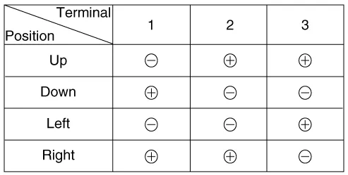
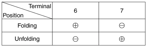
| 4. | Apply battery voltage to each terminal as shown in the table and verify that the mirror operates properly. [Mirror Control (LH/RT)]
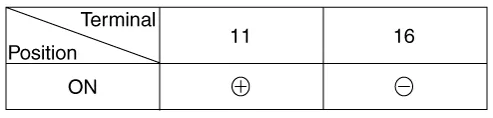
[BSD Indicator]
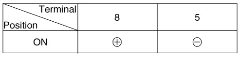
[Mirror Heater]
[Side Repeater Lamp]
[Mirror Fording Motor]
|

| Removal |
| 1. | Disconnect (-) battery terminal. |
| 2. | Remove door mirror assembly. (Refer to Body - "Outside View Mirror") |
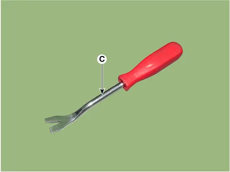
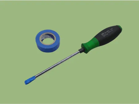
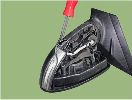
| 3. | Using a fastener remover (C), remove the mirror (A) as illustration below.
|
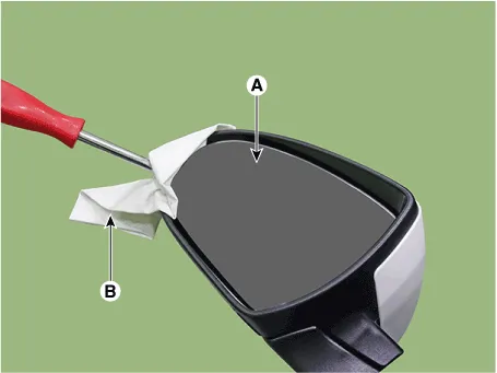

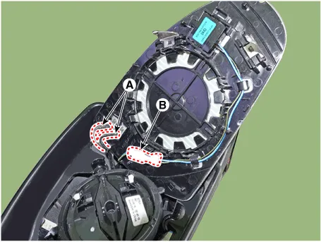
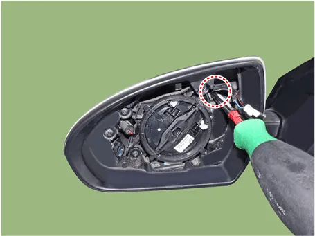
| 4. | Disconnect heat wire connectors (A),(B) and then remove the mirror.
|
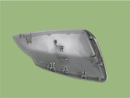
| 5. | Remove the scalp.
|

| 6. | Remove front cover and LED side repeater lamp lock screw.
|
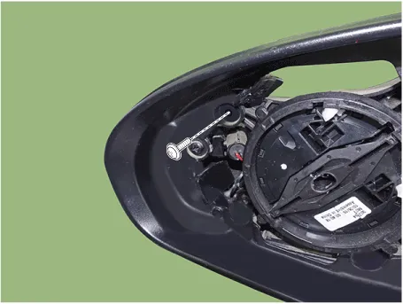
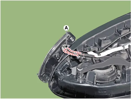
| 7. | Using a fastener remover, remove the LED side repeater lamp as illustration below.
|
| 8. | Disconnect the connector (A) and then remove the LED side repeater lamp (A).
|
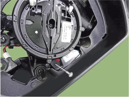
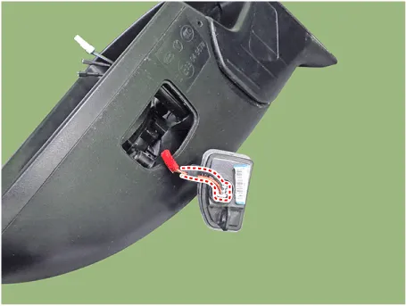
| 9. | Loosen the puddle lamp mounting screw.
|
| 10. | Using a fastener remover, remove the puddle lamp (A) as illustration below.
|
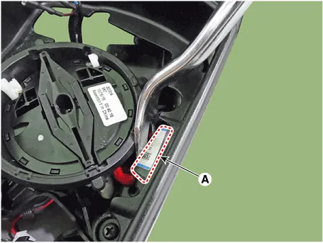
| 11. | Disconnec the connector and then remove the puddle lamp.
|
| Installation |
| 1. | Install the puddle lamp. |
| 2. | Install the LED side repeater lamp. |
| 3. | Install the scalp.
|
| 4. | Connect mirror heat wire connector and BSD connector then mount mirror. |
| 5. | Install the door mirror assembly. |
| 6. | Connect (-) battery terminal then check if door mirror lamp works normally. |
Components1. BSD Indicator2. Side repeater lamp3. Puddle lamp
Other information:
Hyundai Ioniq (AE) 2017-2022 Service & Repair Manual: Duct Sensor. Repair procedures
Inspection1.Check that the voltage values of No. 1, 2 duct sensors change1. Sensor (+ 5V)2. Sensor groundSpecification Ambient temperature [°C (°F)] Resistance (kΩ) Voltage (V) 50 (122)1.
Hyundai Ioniq (AE) 2017-2022 Service & Repair Manual: Smart Cruise Control (SCC) Switch. Components and components location
C
Categories
- Manuals Home
- Hyundai Ioniq Owners Manual
- Hyundai Ioniq Service Manual
- Troubleshooting
- Jump starting procedure
- Brake System
- New on site
- Most important about car

Copyright © 2026 www.hioniqae.com - 0.0199