Hyundai Ioniq (AE): Power Door Mirrors / Power Door Mirror Switch. Schematic diagrams
Hyundai Ioniq (AE) 2017-2022 Service & Repair Manual / Body Electrical System / Power Door Mirrors / Power Door Mirror Switch. Schematic diagrams
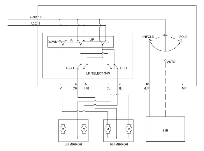
| Circuit Diagram |
Inspection[Power Window Switch]1.Disconnect the negative (-) battery terminal.2.Remove the driver door trim.(Refer to Body - "Front Door Trim")3.Disconnect the power mirror switch connector from the door trim.
Other information:
Hyundai Ioniq (AE) 2017-2022 Service & Repair Manual: Evaporator Temperature Sensor. Repair procedures
Inspection1.Turn the ignition switch OFF.2.Disconnect the evaporator temperature sensor connector.3.Measure the resistance between terminal "+" and "-" of the evaporator temperature sensor.Specification Evaporator core temperature [°C (°F)] Resistance [KΩ]
Hyundai Ioniq (AE) 2017-2022 Service & Repair Manual: Components and components location
C
Categories
- Manuals Home
- Hyundai Ioniq Owners Manual
- Hyundai Ioniq Service Manual
- Brake System
- Hybrid Control System
- Maintenance
- New on site
- Most important about car

Copyright © 2026 www.hioniqae.com - 0.0186