Hyundai Ioniq (AE): Seat Electrical / Power Seat Motor. Repair procedures
Hyundai Ioniq (AE) 2017-2022 Service & Repair Manual / Body Electrical System / Seat Electrical / Power Seat Motor. Repair procedures
| Inspection |
Diagnosis with GDS
| 1. | The body electrocal system can be quickly diagnosed failed parts with vehicle diagnostic system (GDS). The diagnostic system (GDS) provides the following information.
|
| 2. | Select the 'Car model' and the system to be checked in order to check the vehicle with the tester. |
| 3. | Select the 'Power seat module (PSM)' to check the power seat module (PSM). |
| 4. | Select the 'Current Data" menu to search the current state of the input/output data. The input/output data for the sensors corresponding to the power seat module (PSM) can be checked. |
| 5. | If you will check the power door lock operation forcefully, select "Actuation test". |
Power Seat Motor
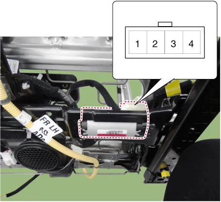
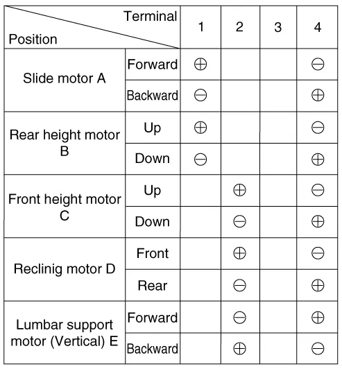
| 1. | Disconnect the connectors for each motor. [Slide Motor]
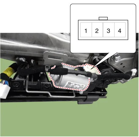
[Rear Height Motor]
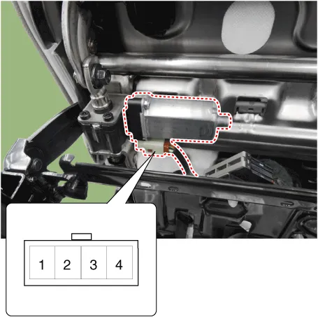
[Front Height Motor]
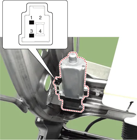
[Reclining Motor]
[Lumbar Support Motor]
|
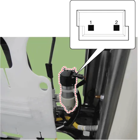
| 2. | With the battery connected directly to the motor terminals, check if the motors run smoothly. |
| 3. | Reverse the connections and check that the motor turns in reverse. |
| 4. | If there is an abnormality, replace the motors. [Driver / Assist]
|
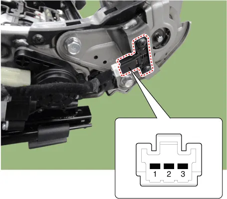
[Reclining Motor Limit Switch]
|

| 1. | Disconnect the limit switch and operate the limit switch. |
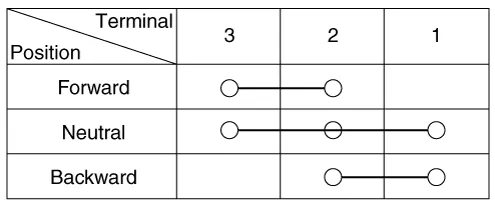
| 2. | Check for continuity between the terminals. |
| 3. | Make sure that the seat operation is normal in the reverse after the maximum operation. |
| 4. | If there is an abnormality, replace the limit switch.
|
| Remove |
Front Seat
| 1. | Disconnect the battery terminals. |
| 2. | Remove the front seat assembly. (Refer to Body - "Front Seat Assembly") |
Component Location1. Lumber support motor (Front/Rear)2. Rear height motor3. Reclining motor4. Slide motor5. Front height motor6. Reclining limit switch7.
Circuit Diagram
Categories
- Manuals Home
- Hyundai Ioniq Owners Manual
- Hyundai Ioniq Service Manual
- Engine Clutch System
- Brake System
- Engine Mechanical System
- New on site
- Most important about car

Copyright © 2026 www.hioniqae.com - 0.0243