Hyundai Ioniq (AE): Front Axle Assembly. Front Hub / Knuckle / Repair procedures
| Removal |
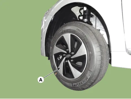
| 1. | Loosen the wheel nuts slightly. Raise the vehicle, and make sure it is securely supported. |
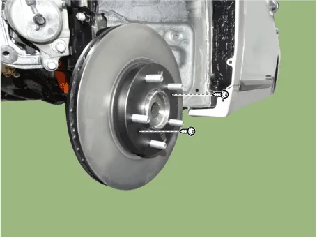
| 2. | Remove the front wheel and tire (A) from the front hub.
|

| 3. | Remove the front brake caliper. (Refer to Brake System - "Front Disc Brake") |
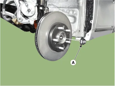
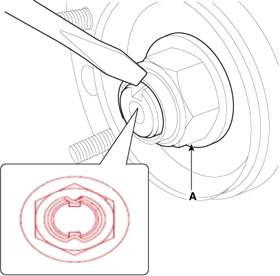
| 4. | Loosen the driveshaft caulking nut (A).
|
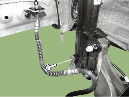
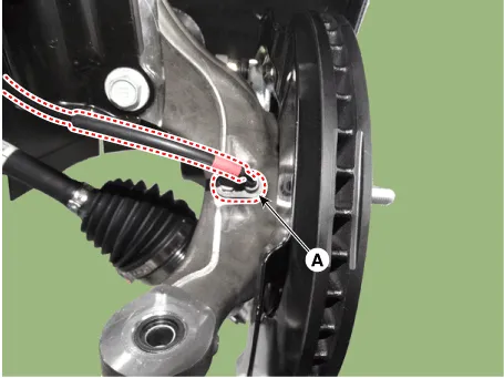
| 5. | Loosen the brake hose mounting bolt and then remove the brake hose bracket.
|
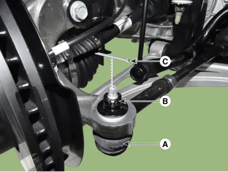
| 6. | Loosen the bolt and then remove the wheel speed sensor (A).
|
| 7. | Remove the tie rod end ball joint.
|
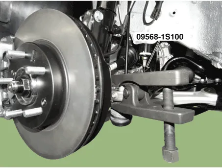
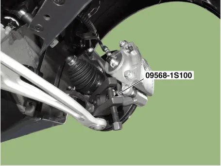
| 8. | Loosen the lower arm nut and then remove the lower arm ball joint by using SST(09568-1S100).
|

| 9. | Loosen the screw and the remove the front disc.
|
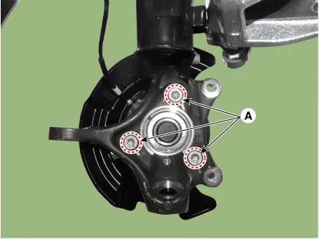
| 10. | Remove the hub bearing by loosening the mounting bolts (A).
|
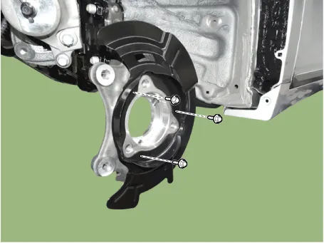
| 11. | Loosen the bolts and then remova the dust cover.
|
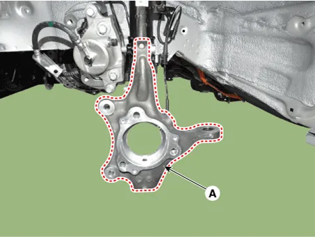
| 12. | Loosen the strut mounting bolts & nuts then remove the knuckle assembly (A).
|
| 13. | To install, reverse the removal procedure |
| 14. | Check the alignment. (Refer to Suspension System - "Alingment") |
| Inspection |
| 1. | Check the hub for cracks and the splines for wear. |
| 2. | Check the brake disc for scoring and damage. |
| 3. | Check the knuckle for cracks. |
| 4. | Check the bearing for cracks or damage. |
Components1. Knuckle2. Dust cover3. Hub bearing4. Brake disc
Other information:
Hyundai Ioniq (AE) 2017-2022 Service & Repair Manual: Specifications
S
Hyundai Ioniq (AE) 2017-2022 Service & Repair Manual: Repair procedures
Removal1.Disconnect the negative (-) battery terminal.2.Remove the tailgate lid trim.(Refer to Body - "TailGate Lid Trim")3.Disconnect the Rear view camera connector (A).4.Remove the Rear view camera assembly after loosening the mounting screws.Installation1.
Categories
- Manuals Home
- Hyundai Ioniq Owners Manual
- Hyundai Ioniq Service Manual
- Transmission Gear Oil. Repair procedures
- Engine Clutch System
- Hybrid Vehicle Engine Compartment
- New on site
- Most important about car

Copyright © 2026 www.hioniqae.com - 0.016