Hyundai Ioniq (AE): Heated Steering wheel / Schematic diagrams
Hyundai Ioniq (AE) 2017-2022 Service & Repair Manual / Steering System / Steering wheel / Heated Steering wheel / Schematic diagrams
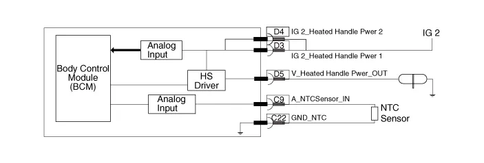
| System Circuit Diagram |
| Body control Module |
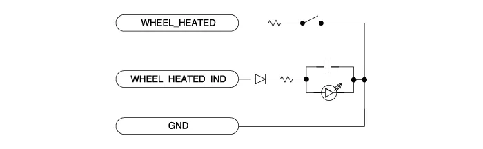
| Heated steering switch |
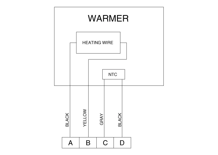
| Heated steering pad |
| Termainal function |
| Body control module |
|
Pin
|
Function
|
| D3 | Ignition 2_Heated handle power |
| D4 | Ignition 2_Heated handle power_2 |
| D5 | Heated handle |
| C22 | NTC (-) |
| C9 | NTC (+) |
| C4 | Heated handle switch |
| Heated steering wheel pad |

|
Housing
|
Pin
|
Function
|
Wire color
|
| Pad | A | Ground | BLACK |
| B | HEATER | YELLOW | |
| C | NTC+ | GRAY | |
| D | NTC- | BLACK |
| Heated steering wheel switch |

|
Pin
|
Function
|
| 7 | Wheel heated |
| 12 | Wheel heated IND. |
| 1 | Ground |
Specifications Item Specification Voltage13.5 VHeated pad resistance1.8 Ω ± 0.2 Ω NTC resistance10.
Removal1.Disconnect the negative (-) battery terminal.2.Remove the glove box.(Refer to Body - "Glove Box Upper Cover Assembly")3.Remove the smart key unit.
Other information:
Hyundai Ioniq (AE) 2017-2022 Service & Repair Manual: emperature Control Actuator. Description and operation
DescriptionThe temperature control actuator is located at the heater unit. It regulates the temperature by the procedure as follows. The signal from the control unit adjusts the position of the temperature door by operating the temperature switch. Then the temperature will be regulated by the hot/cold air ratio decided by the position of the temper
Hyundai Ioniq (AE) 2017-2022 Service & Repair Manual: Cruise Control Switch. Components and components location
C
Categories
- Manuals Home
- Hyundai Ioniq Owners Manual
- Hyundai Ioniq Service Manual
- Hybrid Control System
- Theft-alarm System
- How to Connect Portable Charger (ICCB: In-Cable Control Box)
- New on site
- Most important about car

Copyright © 2026 www.hioniqae.com - 0.0168